Sherwood Ranger - Make Parts - 10B
*This web site is NOT owned or managed by G-TLAC. G-TLAC is not responsible for the content unless explicitly stated. See Disclaimer.
Split from the prior square tube / u-channel make parts page...
10/16/11 - cut firewall beam insert blanks
The purpose of this page is to document fabrication of a couple more u-channel type parts by bending them up from flat stock. The plans call for 1.25x1.25x.125 to have two sides machined to half-thickness, yielding a U-channel with a dimension of 1.125 across the sides of the U. In looking closer at the plans, this is done in three places. 2 small U-channels below the control stick torque tube, 2 slightly longer u-channels over the top of the control stick torque tube, and at 4 places at either end of the upper and lower firewall cross-beams.
For the ones over the top of the control stick torque tube, all these are doing is closing off the .050 plates forward and aft of the two main fuselage frames - meaning they permanently restrain the torque tube from being lifted back out of the fuselage (well, as permanent as drilling out some rivets). So the effort to machine down 1.25 u-channel seems excessive, given the function of the parts - a U with cross section thickness of .062 all around should be sufficient. These aren't even all that tight-tolerance. Obtaining an outside dimension of 1.125 on the U should not be too difficult with the little bench-top brake.
For the ones below the control stick torque tube, these then have .125 doubler plates inserted into the insides of the U. Purpose here is to provide a larger bearing area for the bolts that retain the control stick torque tube. I'm not sure if the bolts turn with the torque tube, but I would think so, given they are constrained on each end with brackets on the torque tube itself. So the doubler plates added inside these brackets provide more bearing area. Again, should not be a big deal to bend these up from .062, then make up the doubler plates.
For the ones at either end of the firewall cross-beams, I have already varied from the plans with slightly thicker material in the beams themselves (plans call for 1.5x1.5x.062 wall, I used 1.5x1.5x.125). The plans also call for a very odd-dimensioned U channel part to be hogged out of bar stock, I guess, since the to-plans U would need a 1.375 outside dimension, a .125 wall per side thickness, for a 1.125 inside dimension. What goes inside of here is are 1" od tubes, with a .062 gusset plate on either side of the tube, for a 1.125 stack height. My build has a 1.25 dimension inside the U, so a make-my-own bracket with an outside dimension of 1.25, inside of 1.125, and material thickness of .062 will be just right (same U size as the other two locations above). Perhaps the factory didn't do this because their firewall cross-beams are slightly lower weight, but I could not obtain 1.5 square tube in 6061 material at 1/16" thickness.
So this page is to document how I avoid machining 1.25x1.25x.125 u-channel completely.
Another part type I want to at least try myself before hiring a shop are a couple of wedge-shaped plates. These are fairly small, 31.5 x 60 and 31.5 x 55 (mm), .062 and .125 thick. Way it works is if one sands away 50% of the material across 31.5mm, the .062 part results in a 3 degree wedge, and the .125 part results in a 6 degree wedge. These are attached below/above the U-channel parts on the forward and aft sides of the center fuselage box to provide the taper for the tail cone and forward fuselage respectively.
10/16/11 - U-brackets
3/4 hr - made up the 4 custom-section U brackets for the firewall cross-beams. Took a couple of calibration parts - I had some ~30mm wide .060 straps left over from another project that I cut a couple of lengths from and calibrated the bends. Got it dialed in so these are just snug inside the firewall cross-beams. Couldn't fit much nicer.
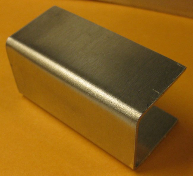
DIY u-channel, flat stock style.
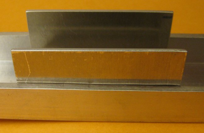
Test fit in one of the cut-off pieces from the firewall cross-beams.
Ok, you got me. One flaw to my bending process - one side of the U is a little taller than the other. If this is an issue, I can bend some more, now that I have the brake calibrated. But the fit is better than I thought I could achieve.
10/17/11 - practice brackets
1/2 hr - I wrote it above, then didn't do it. Made the other 4 brackets at 1.25 outside dimension, just like the 4 for the firewall beam. But they are supposed to be 1.125 across the outside. Oh well, more practice hitting a dimension. They're right on - just the wrong number. Aluminum doesn't cost much - do over.
10/18/11 - more brackets
1/2 hr - Ok, so now they are dimensionally corrected. For whatever reason, the brake was a little less happy with the wider pieces - one slipped, and the bend radius is a little funky. Might need to try these yet one more time. The narrower ones are ok, but I have an idea for the radius that if I like it, I might have to make all of these again.
10/24/11 - brackets to firewall beams
3/4 hr - Drilled the U-brackets to the firewall cross beams. Deburred the insides of the U and clecoed the gusset plates inside these. There is a little gap due to the radius of the u-bracket, so I will need to slightly round off the outer edge of each of the gusset plates so they sit flat inside the U-brackets. Also spent a few minutes on the short fishmouthed tubes. These are doubler tubes where a dimension wasn't quite clear. So removed a little more material from each to get them to line up with the mating parts (these go in the forward fuselage).
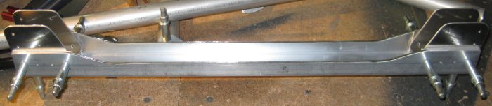
U-channel with u-brackets and gusset plates.
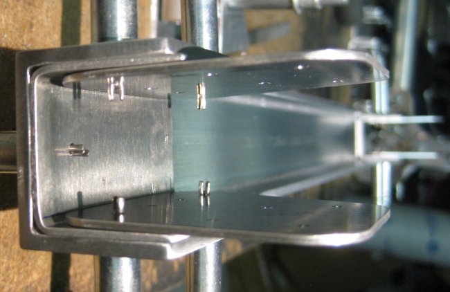
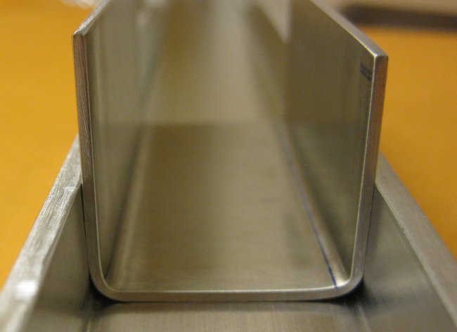
End view, u-channel assembly. Inside dim = 1.0". Outside dim = 1.5".
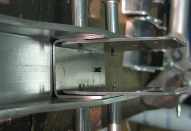
Center looking outboard, u-channel assembly.
10/25/11 - Angle plates
1 hr - tried making the .062 and .125 angle plates. Cut some strips, extra long to have a handle. Changed the sanding belt on the belt sander to a 40? grit in order to attempt to remove more material more quickly. Since each part gets very hot very quickly, I alternated between parts and got maybe half of each part done.
10/26/11 - Angle plates
1/4 hr - sanded some more on the angled plates until they got hot, then worked the forward fuselage.
6/17/12 - Angle stock parts
1/2 hr - made up some cardboard patterns for a couple of the angle stock parts. These are FP13 and CC15. Near as I can tell, these and UA16 R&L are the only parts to be made from 2x2x.125. Actually 2x1x.125, but I can't get that. FP13 - attaches a rudder cable fairlead, and joins the seat rail to a tube up to the upper longeron, plus another hole that I have not determined what it's for. CC15 is the attach point for the elevator pushrod pivot. The pivot - has the elevator pushrod out of the control stick on the forward side, and opposed cables off the aft side to drive the elevator. The UA16 are to attach the brake actuation cable to the brake near each wheel.
6/18/12 - Angle stock parts
1 hr - marked and cut out the FP13 and CC15. Not really sure why I'm doing this now, other than I recently got a little angle stock in with an order of clecoes. And these go into the aft fuselage, which is the next major section I will work on.
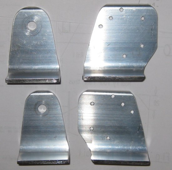
CC15 on the left, FP13 (R&L) on the right.
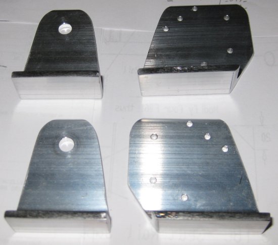
Did not drill holes in the mounting flange. They are shown for the FP13, but because I used a larger rectangular tube for the seat support beams, I will locate and drill these on the assembly.
Click to join sherwoodbuilders