Sherwood Ranger - Fuselage - 1
*This web site is NOT owned or managed by G-TLAC. G-TLAC is not responsible for the content unless explicitly stated. See Disclaimer.
First page of fuselage construction. Center fuselage box.
8/18/11 - Forward fuselage frame
1/2 hr - I don't have nearly all the brackets that go on this frame, but I wanted to get some idea how big this is, and see if my marking and drilling are remotely accurate. So far, it looks pretty good. The pre-drilled plates lined up to the holes in the tubes. I think I would like to complete this frame as much as possible and maybe hang it out of the way, just to get some tubes sorted out and set aside. Then maybe do the other frame, and set both frames aside with the tubes that go between the two frames.
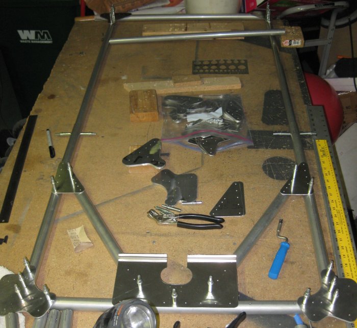
Tube near the top goes inside the top tube. Will need to debur inside the outer tube so the inner tube can slip in for drilling.
8/20/11 - Forward fuselage frame
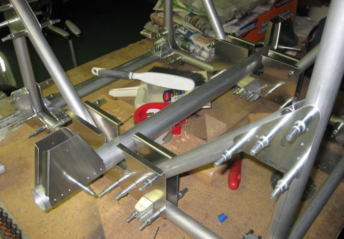
1/4 hr - The way the pilot holes are set up for the triangular gussets at the upper end of the diagonal tubes, in order to pivot these triangular gussets to be on the centerline of the vertical tubes, I had to file small relief in the diagonal tubes the one on the right at the photo was touching the vertical at the upper end of the diagonal, and the one on the left was touching the bottom tube. With that done, the triangular gussets rotated right onto the tube centerline. In addition, I had to remove the cleco at the lower end of each diagonal tube to allow it to translate a little. This means the pilot holes were a little off, but no big deal since I have a 5/32 pilot hole that eventually is drilled to #12 for the 3/16" rivet. So I held the lower diagonal tubes in position and re-drilled an initial location hole one hole up the lower plate, allowing the holes at the ends of the diagonal tubes to just be misaligned. Again, this will disappear when the holes are up-sized for the rivets.
8/21/11 - Forward fuselage frame
1/4 hr - turned the frame over and started drilling on the gusset plates for the back side. Finished that, taped the tube that goes inside the top cross tube to the frame so it wouldn't get misplaced, and set the forward frame aside.
1/4 hr - sorted out the parts for the aft frame and started drilling those parts together.
8/22/11 - Aft fuselage frame
1/2 hr - drilled the gusset plates to the first side, turned it over and drilled the parts to the 2nd side. Set the whole frame aside.
8/28/11 - Aft fuselage frame
1/2 hr - drilled chamfered upper (short) tubes into the framework. Turned it over and drilled these tubes to the gussets on the other side. Started to drill some of the holes between the pilot holes, but it's too hot, and the chuck on the drill I'm using is too wide - it rubs on the clecoes of the drilled holes to either side. So I'll put the bit in the other drill and do these holes when it's a little cooler.
8/29/11 - Aft fuselage frame
1/2 hr - drilled thru the remaining pilot-size holes in this frame. Put it aside. Cleaned up the work table. Brought the forward frame back to the table to put the chamfered short upper tubes into place. Got these pilot drilled into position on one side. Plan is to drill the remaining pilot size holes on this side, flip it, and drill the pilot size holes on the other side.
8/30/11 - Forward fuselage frame
1/2 hr - drilled the pilot holes in one side, flipped it, drilled the pilot holes in the other side. Pulled off the top cross tube, deburred the holes inside each end with a round file. Slipped the second tube (1.0 od) inside this tube and drilled the pilot size holes through it. Then re-clecoed the now doubled upper cross tube back to the frame. That's about all I can do with these for now.
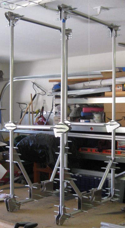
Uh, I hope those are supposed to be different heights. Didn't notice until NOW. The assembly print for the aft frame does NOT have a reference height dimension. The print for the forward frame DOES, and I checked it.
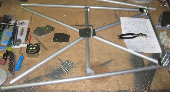
Forward fuselage frame.
Aft fuselage frame. Yes, it is supposed to be shorter.
8/31/11 - Forward fuselage frame
1/4 hr - realized I hadn't chamfered the longer vertical tubes that form the bottom sides of this frame, so un-clecoed them, pulled them out, made the chamfers, and stuck them back in. Chamfering with a disk sander and Scotchbrite wheel is WAY simpler than any sort of lathe-based operation that I can imagine - and uses tools I already have...
Also ran across a build log of a Baslee / Nieuport builder - 4 days to fuselage assembled, on the gear, engine mount located and drilled, and all wing ribs bent. Must be nice. Very much lighter construction than the Ranger, though.
9/1/11 - Forward fuselage frames
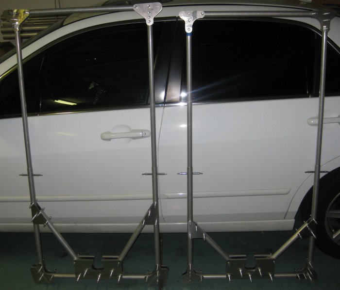
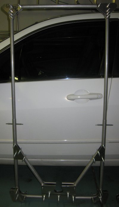
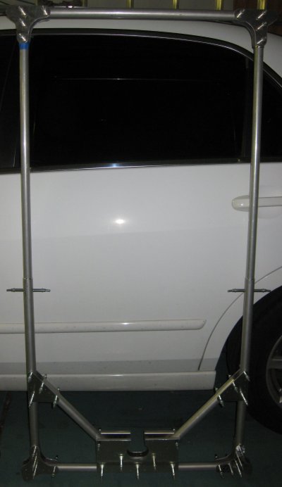
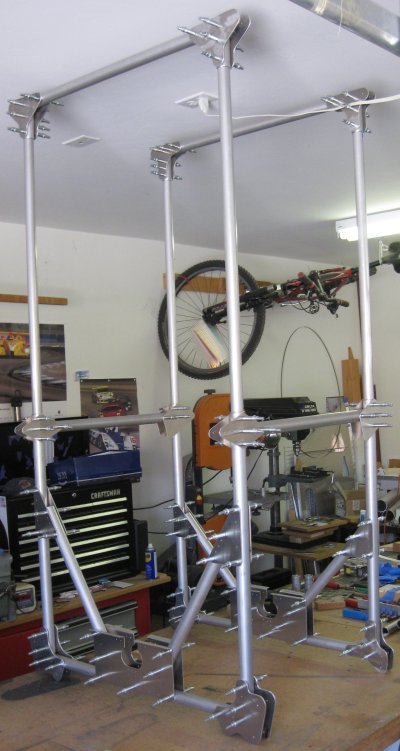
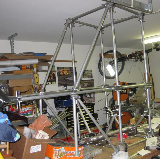
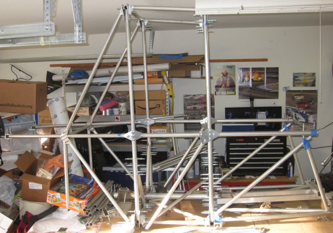
1/2 hr - drilled the gusset plates halfway up the frames to the frames. Alignment trick - used a small block of MDF with a 90 degree angle to set on the tube, align the row of holes in the gusset with the block, drill the plate to the tube. Got 7 out of 8 plates straight - one rotated as I drilled, so I will see if I can adjust the pilot holes (should completely disappear in drilling from 3/32 to 3/16) then stood up the 2 frames on the bench and clecoed the F7 tubes in place. It's not stable or triangulated, but gives an idea how big this fuselage is going to be. Looks nice and wide - 26 3/4" to the outsides of the tubes, and actual elbow room will be larger than that because stringers go outside the tubes and the fabric outside of that.
Shows how far apart these sit, and also shows that I'll probably need to make a lower bench to support this on when it grows farther forwards and aft. It does clear the ceiling, but not by enough to easily move it.
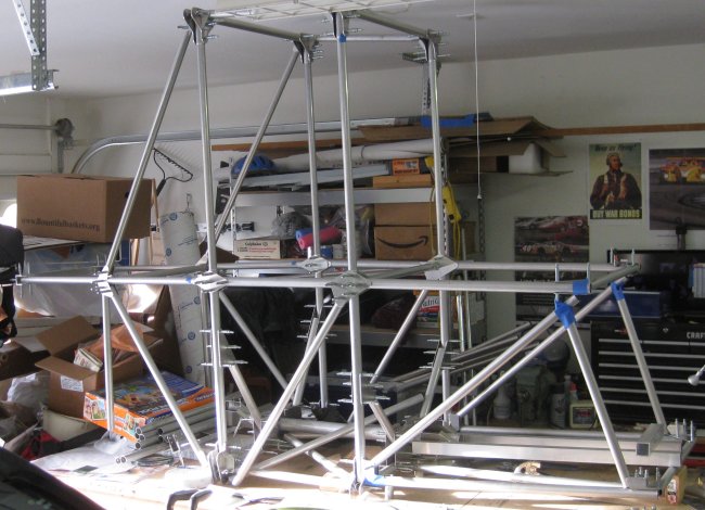
10/2/11 - Didn't do much here (after adding a bunch of U-channel brackets) - just laid in the control column tube. View from the left side, angled aft.
10/2/11 - View from the right side, angled looking forward.
10/3/11 - Forward fuselage
1/2 hr - sorted out the forward fuselage tubes and did a quick layout to see the size of this portion of the fuselage.
10/25/11 - Forward fuselage
1/2 hr - fish-mouthed a couple of tubes that go towards the front. Tweaked the doubler tubes that go at the aft end of these a little more so the holes line up with the joiner plates. Got the two tubes pilot drilled into position, then set the firewall cross beam across the front. With this shape lifted up off the table, there seems to be a lot of length from the forward seat to the firewall.
10/26/11 - Forward fuselage
1/2 hr - added 4 more tubes to the forward fuselage. Identified yet another one that I did not cut. Then I found my cut list, and there it was, not checked off. I guess I was going through the cutting pretty quick. Other than getting some tubes out of the way by getting them off the table, and making obvious ones that didn't get cut, it's really to the point where I need to have some of these assemblies bolted/riveted as the whole thing is out of places to cleco onto.
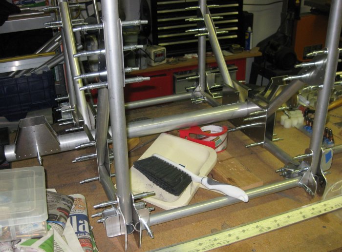
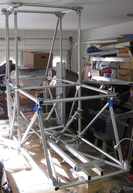
Section forward of the central box going on. This sticks out farther than I thought - should be plenty of leg room in the forward pit.
From the other side. I noticed tonight the weight of this is making the front end sag down - there is no diagonal in the central box to keep the entire central box from leaning forward. No where to cleco in a diagonal tube without un-clecoing the bracket it would join onto...
10/27/11 - Forward fuselage
1/2 hr - now it's to the point of just mocking up to see if there are any parts I missed. Added some tubes to the aft side of the central box in order to get an idea how big the pilot's pit is. Looks pretty big. But similar to above, without making some permanent assemblies, the structure quickly runs out of places to cleco parts on. Though on the upper pilot's cockpit side tubes, there's a pair of holes at the aft end of each one which lined up exactly with the .050 bracket and .125 U channel parts that stack together there. So though this airplane isn't really designed for plans building, with accurate drilling, the parts will go together.
10/28/11 - Forward fuselage
1/2 hr - got about as far as I could get with hanging/setting tubes on it. At this point, it's only for checking that I made the correct quantity of parts. The main parts needed to be able to put this together (aside from fasteners) are some tube inserts, angled plates, a pair of saddles, and some little L brackets that need a curved channel cut into one side. So not a lot of lathe/mill machining needed to this point.
Out the right side of this view - the next tubes are the tail cone longerons - about as long as the entire structure assembled here. On the left side - that is the firewall, so forward of that is engine mount and engine.
That one tube laid diagonally across the middle of the central box, leaning over the top of the larger-diameter control stick torque tube actually triangulates the very top box up near the ceiling.
One thing I get from mocking it up like this is that the cockpits appear to be larger than I thought they might be. Those rectangular cross-section tubes are what the seat sits on. They are too low in this photo - the seat is a bit higher off the bottom of the structure.
10/29/11 - Back up to go forward
1/2 hr - cut / recut tubes. One thing the mock up showed me was that 3 tubes were missing. I checked the spreadsheet again, and sure enough, I could see one that was not marked off. The other two (two of four needed), the markings were confused, but no tubes. So I dragged out the chop saw, marked, and recut those. Another thing revealed (not sure why I didn't see this before), two of the tubes in the most aft section that I have mocked up had bad graining - almost like the aluminum didn't quite stick together as it was being pushed through the tube extrusion process - like built-in cracks. I looked at other tubes I could see, then thought, check the spreadsheet. There, one other tube was made from that same length. Found it on the tube schematic in the plans, and sure enough, more marks I would rather not be there. So found the left-over length of that size (1.125 x .058), and there was plenty to re-cut those 3 tubes as well. Now that I know what to look for, I will check the others when it comes back apart for the next iteration of assembly. No big deal - I ordered generously on the more common sizes.
1 hr - cut some U-channel brackets that show up in the assembly figures but are not in the quantity defined in the detail part prints. The detailed parts print says to make 4, and those are used on the forward fuselage box frame, then an assembly print at the back of the seat area says to take 4 and modify them to the dimension shown. Well, that means 8 are needed in the airplane, but the detailed part print says to make only 4. Part number is FB61. I adjusted the quantity in my parts spreadsheet. Got them rough cut and holes marked. Still need to smooth edges and drill.
1/4 hr - sanded / scotchbrited these brackets.
10/30/11 - brackets & tubes
1/2 hr - drilled the modified FB61 brackets. Drilled the 3 off 1.0" dia. tubes that I had missed cutting earlier. Didn't feel like adjusting the setup to drill the replacement 1.125 tubes yet.
11/4/11 - tubes and aft central frame
2 hr - re-set the drill press for the 1.125 tubes, drilled those. Disassembled the mocked-up fuselage, and separated the tubes into front, rear, and center sections. Got the upper corner of the aft central frame drilled to final size and partially deburred. I walked it up through the drill sizes and clecoes - #30, #21, #12. Well, turns out the bolts are AN4's, so then drilled those to 1/4 inch. Got the bolts in, so they do pass through the structure even though it was drilled from opposite sides only. Need to disassemble, debur, and reinstall the bolts. Don't have any rivets yet. Was working on calculating grip lengths to order some.
1/4 hr - checked for tube inserts. Quite a few tubes have inserts. The general note at the start of the fuselage chapter says any tube 1.0 dia. or larger with only a bolt through the end needs an insert to increase the bearing surface. This corner is bolted and riveted, so I figured there would be no inserts. But in checking drawing sheet 6 (the tubes), an insert is called out for the FT3 horizontal tube. It isn't a bearing-increase insert, it's an anti-crush insert made of nylon. I made these already, just not drilled to final size. So I will drill one out to .250 and add it inside the end of the tube.
2 hr rivet planning - since this is heading in the direction of needing some permanent assembly, I decided it was time to focus on rivet sizing for a while. I already have rivet sizes (as spec'd in the plans) in the hardware list spreadsheet, but I don't know how these convert to rivets as called out from online suppliers. So I went through most of the figures to get the dimensions of the material stacks to be riveted part-by-part, and checked online for what was available. Turns out it's about $310 worth of rivets. Sonex rivet kit has been $700 for a LONG time, and the Sherwood has about 1/4 as many rivets, but most of them are 3/16 diameter, where most of the Sonex rivets are 1/8. So the cost seems reasonable.
1/4 hr tube insert - got the tube insert drilled and fitted, and the bolt installed.
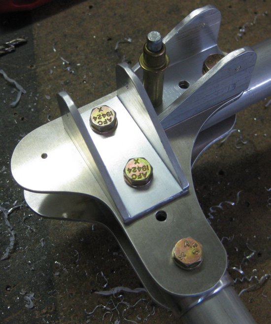
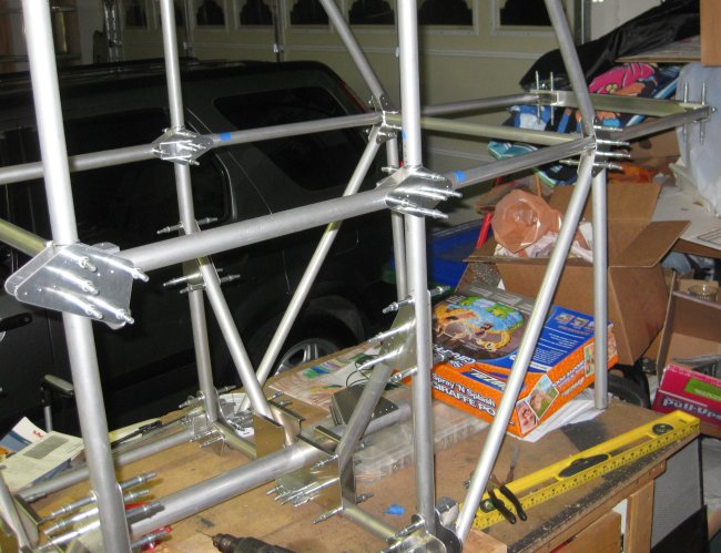
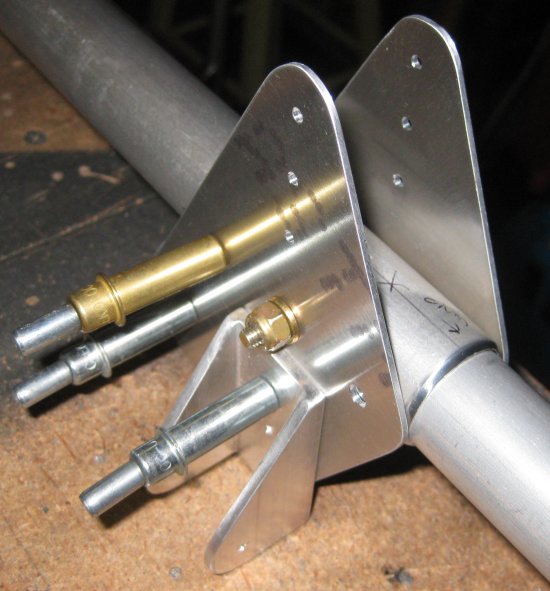
Aft central frame, upper corner, forward side. Empty holes are for 3/16 dia. blind rivets. Lugs on the left, with the small-diameter pilot holes are the aft spar attachment points. The U bracket to the upper right joins the diagonal triangulation brace inside the upper wing center section, and the U bracket to the lower right joins the fore-aft tube between the forward and aft fuselage frames (essentially ties the forward and aft spars together).
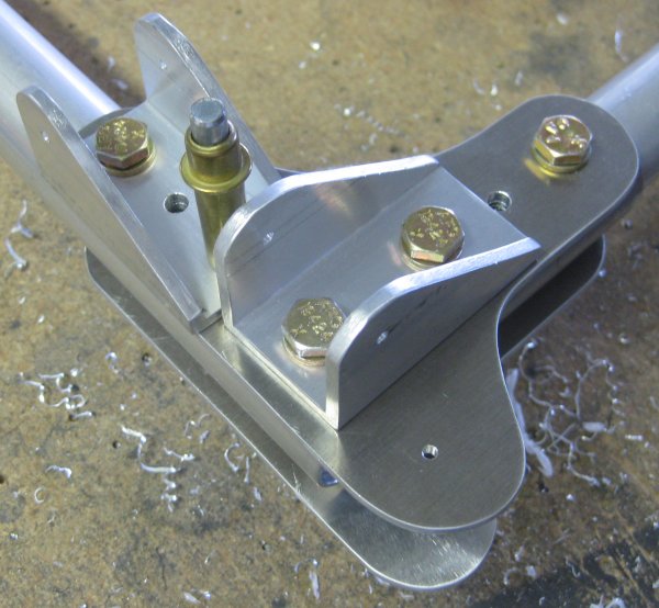
At least this little bit that I have the final fasteners in, it looks like they did a great job with specifying the bolt lengths.
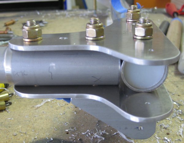
Aft central frame, aft side. Most of this gets buried inside the upper wing center section.
11/5/11 - aft fuselage frame, upper corner fasteners
1/2 hr - drilled and installed fasteners on the other corner. Noticed the first corner had the bracket for the fore-aft tube upside-down. Goes back to the rule I learned as a parts designer - if a bracket has a 2-point (symmetrical) hole pattern, it will be installed upside-down. So un-bolted the bracket on the first corner and turned it around. The photos above have been changed to show the corrected orientation of the bracket.
1/2 hr - drilled a couple more plates to final size on the aft fuselage frame.
11/6/11 - aft fuselage frame
1/2 hr + 1/2 hr later - drilled a few more plates to final size. About to expend my entire stock of 3/16" clecoes. From the prior airplane projects, I have plenty of the 3 smaller sizes, but only about 30 of these. Will check the prices - last big buy was from Panamerican Tools in Ft. Lauderdale. I will see what they are offering these days.
11/7/11 - aft fuselage frame
3/4 hr - drilled a couple more plates to the final size. Did the FB45's on the drill press, since they only have one AN3 hole. Got those bolted on, though probably not for the final time. Out of 3/16 clecoes.
11/8/11 - aft fuselage frame
3/4 hr - drilled part of the bottom corner plates to final size. Main things left on this frame are the bottom corner locations where the angled plates fit into the stack, and the small channel pieces above and below the control torque tube. Mis-read the plan and drilled for AN4's at AN3 location, 2 places where diagonal tube attach brackets attach. Ok, so those bolts will be a little heavier, but other than that, it should work.
Half-way up the frame, left side, outboard looking in. Frame is laying down on the table, so airplane-down = to the right in this view, and airplane-forward = bottom of this view.
Same joint, inboard looking out. Airplane-up is the tube going out the bottom right of this view. I believe the U-channel bracket is for a tube that goes straight across in front of the pilot.
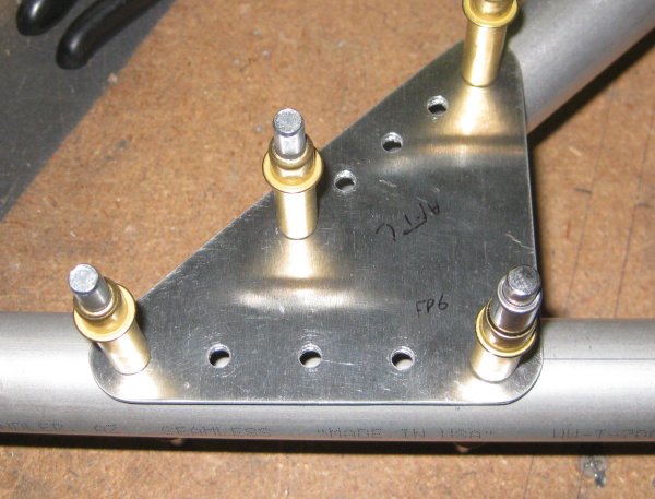
One of the lower diagonal tube brackets. Last airplane I built was mostly 1/8 rivets, so these 3/16's look relatively huge.
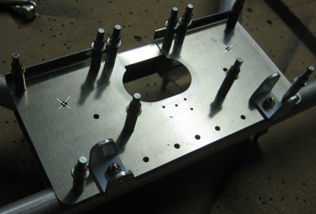
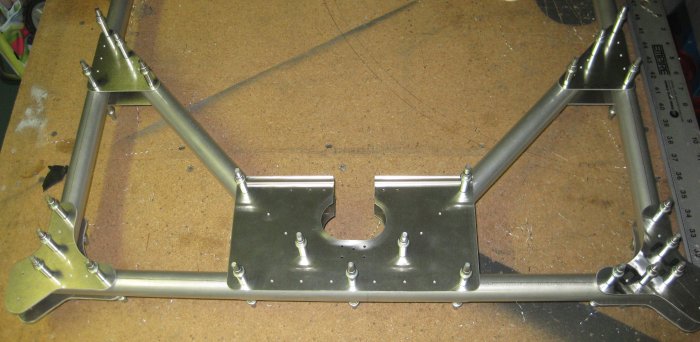
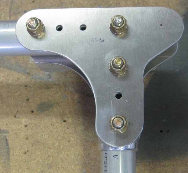
Bottom center plate, aft side. The small U brackets accept diagonals that run under the pilot's (aft) seat. The small pattern of 5 holes below the racetrack-shaped opening is for the control torque tube attach point.
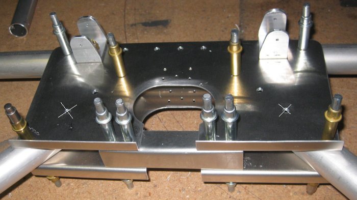
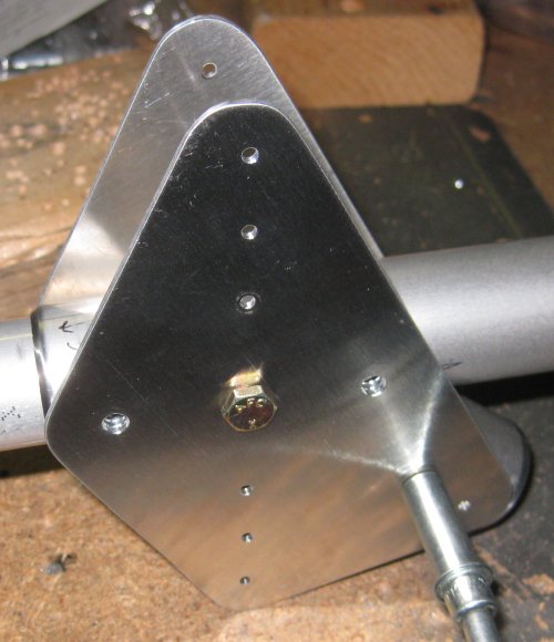
Bottom center plate, angled down from the top. The channel piece with the 3/32 (silver) clecoes just closes off the opening where the torque tube drops through. I don't think anything further attaches to this little channel piece.
Why the X's on the bottom center plate photos? Because those holes ARE NOT SUPPOSED TO BE THERE. I'm not too keen on how this is noted - in the text of the build instructions. Might have been better to just remove those holes from the detailed parts print AND / OR the assembly figures, rather than noting them within many paragraphs of build instructions? But it shouldn't be that big of a deal to work around them. I believe this is a result of a lowering of the seat that I read about in one of the articles. These seat support beams look like they were just made to sit, as one continuous length, over the top of these bottom center plates. Somewhere along the way, it was decided the seat was too high, so split the support beams into two pieces each and hang them from below the flange on the bottom center plates. Pretty easy way to lower the seat 1.5 inches, but details like the drawing for the plates then show holes that don't get used. Oh well.
This page has gotten pretty long. Moving on to Fuselage 2...
Click to join sherwoodbuilders