Sherwood Ranger - Fuselage - 3
*This web site is NOT owned or managed by G-TLAC. G-TLAC is not responsible for the content unless explicitly stated. See Disclaimer.
Fuselage construction will be continuing here...
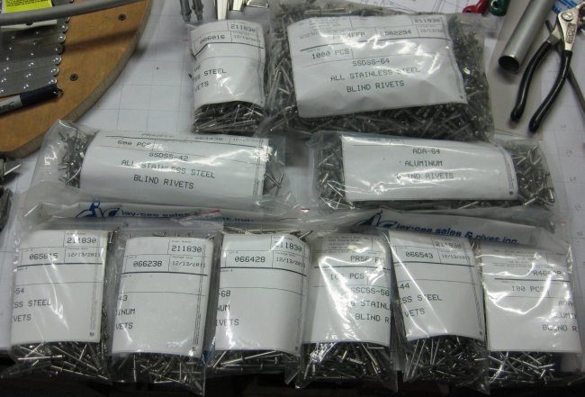
12/19/11 - Rivets arrive
Box of rivets arrives. I had to round up on a couple of sizes, but I think overall I shrank the variety of rivets needed considerably. All packages shown here except for one size which is on ~1 week backorder.
3/10/12 - aft fuselage frame
1 hr - marked and trimmed the angled shims machined earlier today. Though during machining, one of the .062 angled shims got chomped by the mill, I used one of the "blade" pieces I had been making on the belt sander to form the 1" wide shim that backs up the bolt heads, as it was close enough for backing up bolt heads. In particular with the nicely machined part going between the U channel bracket and the .125 plate which forms the corner of the fuselage frame - nice, well-established angle there. So got both aft fuselage frame brackets drilled in place on the angled shims. Need to drill up to final size and install the fasteners required for this frame.
3/11/12 - aft fuselage frame
1/2 hr - drilled U channel brackets with angled shims to final size.
3/12/12 - aft fuselage frame
1 hr - deburred, cleaned off markings, and reassembled the lower corner assemblies.
3/14/12 - aft fuselage frame
3/4 hr - riveted some of the lower portion of the frame. Did the gusset plates at the lower diagonal tubes and the few rivets in the lower corner brackets. Left the bottom center plates un-riveted because there's a few more parts to be drilled in there.
3/15/12 - forward fuselage frame
3/4 hr - riveted the gusset plates at the diagonal tubes to get those clecoes off of there. Set-up and pilot drilled the angle shims at the lower forward U-channel parts.
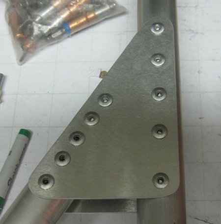
Riveted gusset plate.
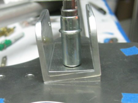
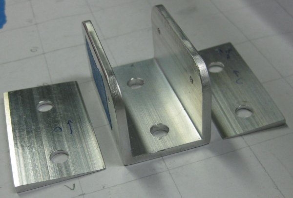
The 6-degree angle shims in position.
6-degree angle shims.
3/16/12 - forward fuselage frame
3/4 hr - drilled the U-channel brackets at the angled shim locations to the frame. Noticed that the nylon tube-filler wasn't in the lower cross tube - will have to add those in (next) before debur and bolting/riveting things back together.
3/17/12 - forward fuselage frame
1/2 hr - disassembled one of the two corners being worked at this point to insert the nylon tube insert. Got that drilled. Deburred all and reassembled. Thought I was missing one of the bolts, but found it on the upper corner - I guess I ran out of the bolt length at the upper corner and was place-holding with the longer bolt. I remember ordering more bolts, so found the correct one for the upper corner and installed that. Don't worry - I'm going to go over all this with a torque wrench - the upper portion all comes back apart anyway to install the rib in the center section.
3/17/12 - frame + center section assy
2 hr - finished the bolting / riveting of the lower corners. Note - install the rivets before the bolts on the U-channel brackets. Otherwise, the rivets are too close to the U-channels for the rivet puller to access. Also installed rivets in the aft side of the lower center plate on the forward frame. Then, in looking at a much later figure, it shows stand-offs for the axial stringers! Crap! I had left the aft frame center plate lower outer corner holes at pilot size specifically because the frame assembly drawing SHOWS the brackets for the stringers, while the forward frame (many more drawings, for some reason) does NOT. Whatever. I'll figure it out. Gathered up the tubes for the between-the-frames area and clecoed some of them into position. It's too tall to do the precision aligning on the table - well, the table is too tall. Will have to figure out how to get this done at another location. And could not locate one of the tubes - I had mocked it up before, so I know it's in the tube collection somewhere. Some of these hole locations are starting to look tough to get to with a drill...
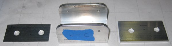
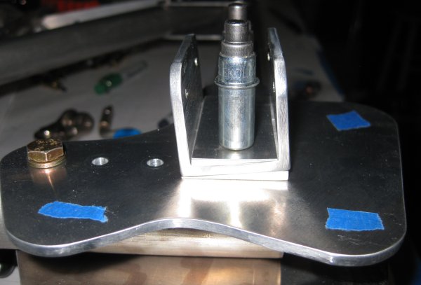
Wedge shims drilled and ready to install.
Wedge shims. Wider one goes below the bracket to angle it, narrower one goes inside the U so the bolts have a level surface to clamp on.
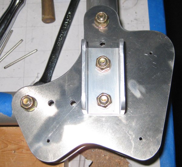
Can not install the rivets closest to the U channel due to interference with the rivet puller and the U channel. So pull the bolts for the U channel, install the rivets, and reassemble.
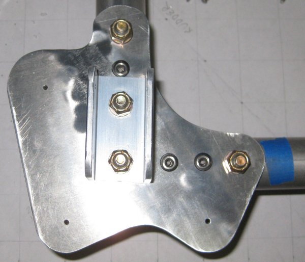
Opposite corner - rivets installed and U channel brackets reinstalled.
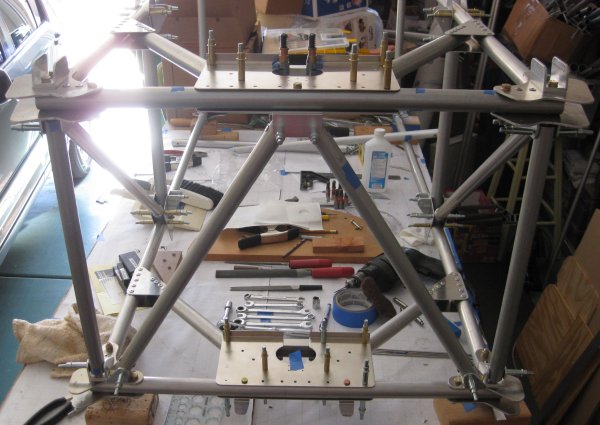
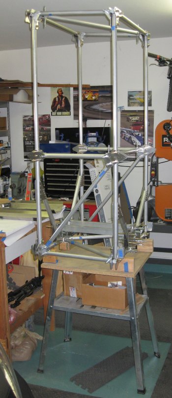
The central box. Passenger seat is right in the middle of this. Forward is to the right.
3/18/12 - center section
1/2 hr - set the center section on the table forward side up, so it's not such a tall structure to work on. Had to figure out where I could put a square on it to align the two frames to be square to the axial longeron tubes. Can get it on the insides of the upper forward corners below the upper longeron (check tube numbers - anyway, it's the only one without gusset plates getting in the way). Tweaked this to be pretty well square, then tried installing the FT6 diagonal tubes that would lock this down. First issue - how to get the tube in there. Had to un-bolt the plate at the upper end of the FT6 to be able to slide that end in from the side. Next issue - the lower end interferes with the bolt on the forward frame. So started filing a clearance cut into the tube. Next issue - it looks like the hole pre-drilled in the other end of the tube is a good bit too far to the long side - maybe 1/4", and the tube interferes with the vertical tube due to its extra length. Will end up drilling this in place, then shortening the FT6 as needed to fit.
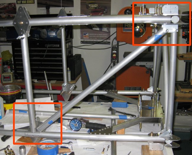
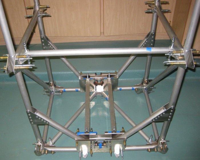
Laid down on the table, forward side up. Airplane up is to the left in this photo. Numbered red squares correspond to photos below.
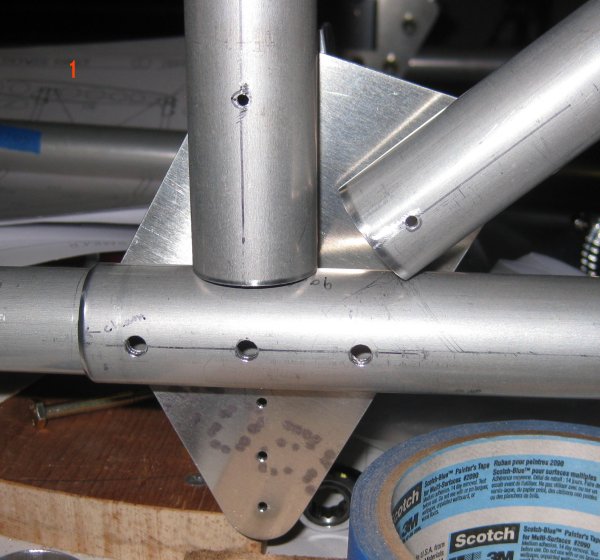
Photo 1 - have to pull off the outer joiner plate at this location to get diagonal tube FT6 into position.

Photo 2 - lower corner - tube FT6 is diagonal out the lower left.
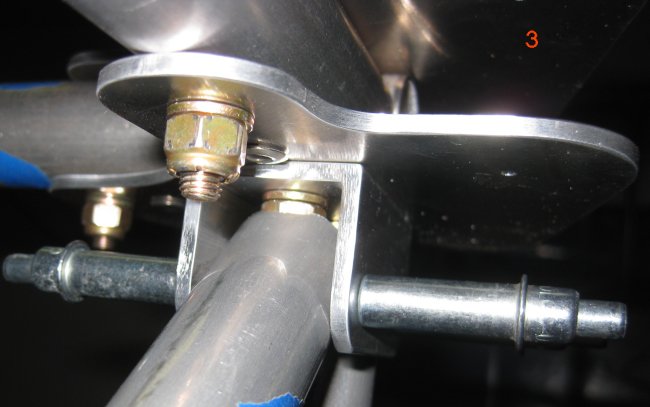
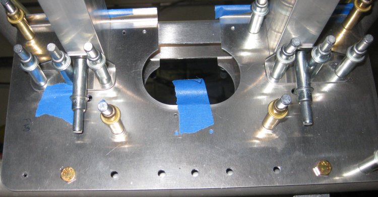
Photo 3 - looking into the U-channel bracket, the tube has to be notched to clear the nut.
3/19/12 - center section
3/4 hr - Figured out FT6. It was RIGHT ON. Turns out, I had not prevented the forward upper joiner plates from rotating, so they cranked around a little. When I straightened these out and added clecoes so they could not rotate, the FT6 is exactly on the length. Of course, I discovered this after drilling it just about 1 hole width off - so I up-drilled one of the two pairs of holes to 3/16 to absorb the extra holes. For the other side, I trusted that FT6 would be right on to length. Most of this time was spent filing notches in the ends of the tubes to clear the nuts on the lower joint plates.
This marks 250 hours I have spent on the project so far.
3/20/12 - center section
1/2 hr - measured the 22mm set backs on the FT10 inserts. Drilled one FT10 for the insert up to full rivet size, deburred, and installed the rivets. This gave one FT10 ready to install and line-drill through the bracket for the attach holes (attach holes on one end are drilled at assembly, but the tube print doesn't say to install the insert first, which is how I figured it would get done). Aligned the fuselage for left-to-right squareness using a 90-degree bubble level - since there isn't a clear place for something as simple as a square to be used. At the bottom end (where the FT10 goes), the structure was already right on. At the top end (in the upper wing center section), it was slightly off, but that's easily pulled back in with the FT11 tube.
3/22/12 - center section
1/2 hr - drilled the inserts for the other FT10 and FT11. Installed these inserts. Drilled the second FT10 into position.
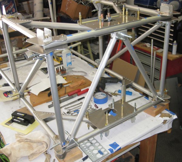
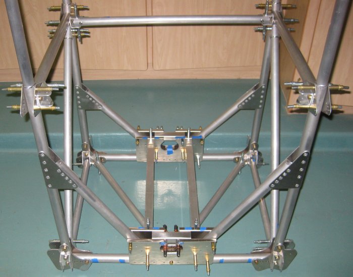
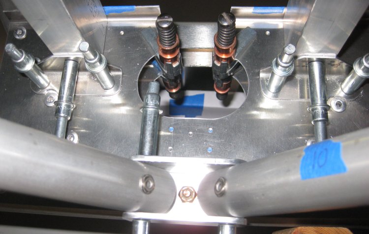
The way the fuselage is laid down on the table, this is looking up at the bottom. The FT10's form the triangle in the bottom. Airplane forward is on the top in this picture.
3/23/12 - center section
1/2 hr - worked on fitting the FT11. This requires filing clearance at both ends for the bolts that attach the FT11 mounting brackets. In addition, it could have helped to only have drilled the bolt hole for the mounting brackets to final size, and drill up the rivet holes when fitting this tube - because the mounting brackets are in 2 different planes. They should be rotated slightly to bring the tube exactly into plane. There isn't a whole lot of force required to bring the tube into the brackets, but the pre-drilled holes on one end don't line up, and it's clear the holes to be drilled at the other end aren't in the same plane as the pre-drilled holes. These differences could be cleared if the brackets are rotated around the mounting bolts slightly. Not a big deal, but something I might note if starting over.
3/24/12 - center section
1/2 hr - continued with FT11. Filed a little relief on each end of the tube - to remove material that would be pressing into the sides of the U brackets. Just a little shave outboard of the mounting holes. Then also filed a slight relief into the U brackets - on the side of each bracket that the FT11 tube presses into. This allowed the tube to angle a little bit in the direction it needs to flex, making for a lower-stress installation. Was just about to drill the holes in the undrilled end and noticed that U-channel bracket HAD rotated around the bolt, so I rotated it back and put a 3/16 cleco in one of its rivet holes so it could not rotate. Got it drilled into position, so started fitting the FT12 tube - lateral tube halfway up the assembly.
3/25/12 - center section
3/4 hr - filed a little more on the FT11 - fits pretty well now. Added in the passenger seat support rails. Since the rectangular tube I could get is slightly larger than what is called out in the prints, I determined that maintaining the outside-to-outside dimension (165mm) is important, because behind the pilot's seat there are several tubes that attach to the outsides of the seat rails. There was nothing obvious that would need to be avoided internal to the seat rails, but I may find something later.

Right side.
Closer in on the right side.
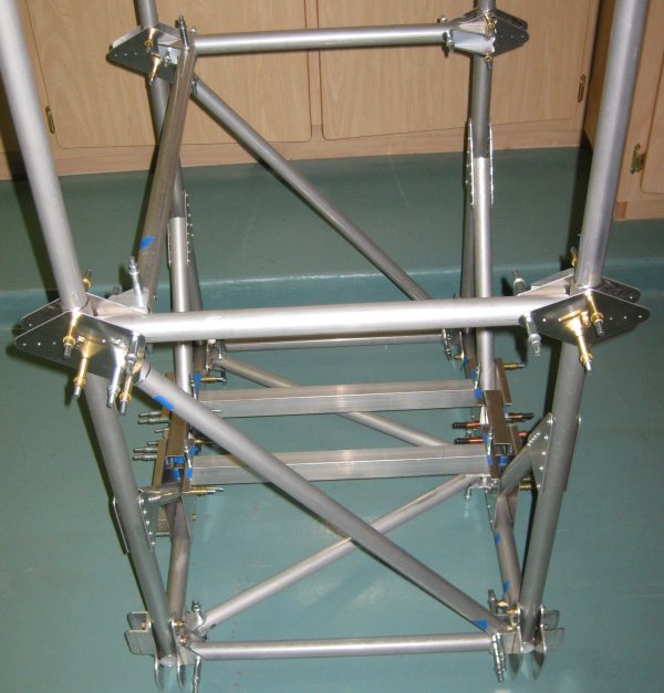
Forward looking aft.
Closer in, forward looking aft.
More or less, the view of the structure from the pilot's seat.
3/26/12 - shop arrangement
1 hr - due to garage door spring breaking, once we got the cars out, I re-arranged the garage to move the lower table to the end where I'm doing the most work, and moved the taller tables down some. The idea is to get a little more clearance to the ceiling with the fuselage upright.
Lower table.
3/27/12 - center section
3/4 hr - continued putting tools back away. Marked / drilled the seat rail support brackets. Drilled one support bracket into position - had to break out the right angle drill attachment, threaded drill bits, and the 12" drill bit. Items inside the bracket are pretty tight.
Seat beam support brackets (silver clecoes).
Seat beam support brackets, other end. Have to file clearance for rivets in these.
3/28/12 - center section
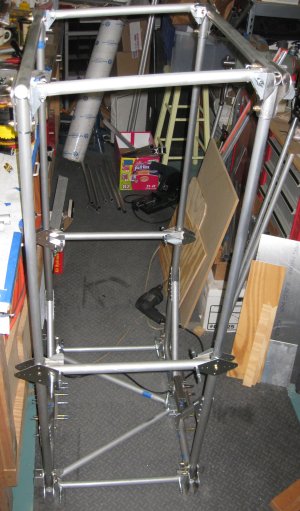
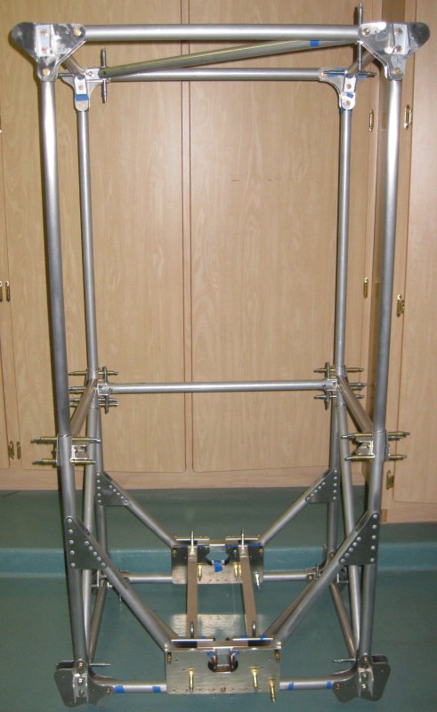
1/2 hr - pilot drilled the remainder of the seat rail support brackets into position. Stood the center section up on the small table and started to figure whether the tubes aft of the center section could be added here or not. Starting to look like this portion has some adjustment capability designed in - that this area also may require the aft longerons (all the way back to the tail post) be in place to line everything up.
3/29/12 - center section
1/2 hr - marked aft foot rest parts for trimming.
3/30/12 - tube inserts
1/4 hr - cut inserts for .049 tubes.
1/2 hr - sanded / scotchbrited / deburred ends of inserts (12 inserts).
3/31/12 - tube inserts
1/4 hr - drilled & deburred inserts in 4 tubes, using 6 inserts. The other 6 inserts go in the aft longerons.
4/1/12 - tube inserts / center section
1/2 hr - riveted the inserts into the tubes. Started up-drilling the fuselage center section. Got part way done with the right outboard side. But overall, MUCH less drilling than with riveted sheet metal construction.
1/2 hr - final-size drilled more of the center section holes. Seems to be maybe 40% done.
4/2/12 - center section
1/2 hr - continued up-size drilling.
4/3/12 - center section
3/4 hr - continued up-size drilling.
4/4/12 - center section
1 hr - completed up-size drilling. Deburred a few locations, installed some bolts because clecoes would be in the way of adjoining tubes.
1/2 hr - forward section
Fitted a couple of the forward section tubes - though I had mocked this up before, now, with bolts in position, tube ends need to be angled / notched for clearance of the bolt heads.
For more forward section, see next page.
Click to join sherwoodbuilders