Sherwood Ranger - Fuselage - 4
*This web site is NOT owned or managed by G-TLAC. G-TLAC is not responsible for the content unless explicitly stated. See Disclaimer.
Continued fuselage construction. Forward of center section.
4/5/12 - forward section
1/4 hr - notched one tube to clear the bolt head. Checked to see how inboard gusset plate lines up relative to outer gusset plate - it's not the same. So not sure what's going on here, or if the geometry of all this drives a difference between the inboard and outboard plates.
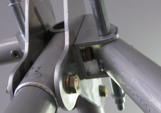
Looking up into upper forward diagonal tubes - trying to show end of tube clearanced for bolt head.
Looking down into lower forward diagonal tube - clearance for bolt head.
Where the upper and lower diagonal tubes join the upper longeron, holes through these plates do not align with all three tubes.
4/6/12 - forward section
1/2 hr - decided to cleco the upper and lower diagonal tubes to the gusset plate and see where the horizontal tube ended up - the hole in the tube is off from the hole in the gusset plate by just a little. So the problem probably isn't as bad as I thought. Started a leveling exercise - if the center section is level front-to-back, then the forward longerons (the horizontal tubes) are leveled to the center section, then that's where they should be. Went around the 4 blocks of wood supporting the center section on the table trying to shim, then decided this is probably a waste of effort until I know that the little table this whole assembly is sitting on is also level. Added the verticals at the gusset plate intersection, then the lower longeron tubes, which angle both inwards and upwards, so there's not a whole lot to reference on these - they fall out where they fall out.
Also re-read the build guide for this portion of the fuselage (and most of the rest of the fuselage chapter as well. For having so many words, it really doesn't speak to details like how to get these gusset plates lined up.
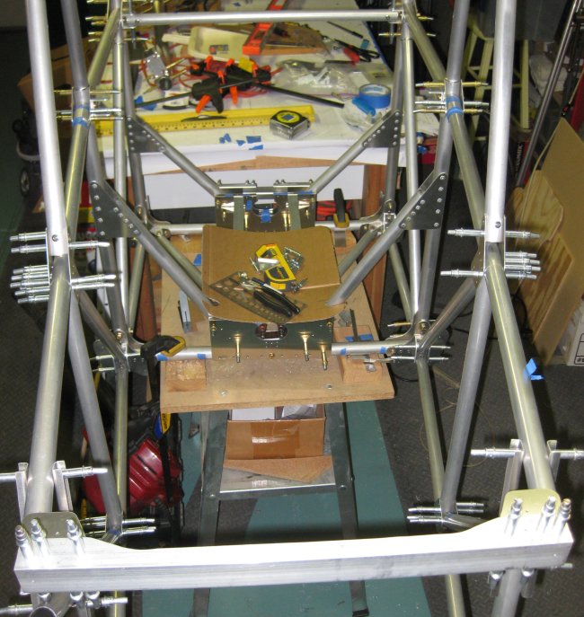
Upper and lower longeron tubes in position. Will need upper and lower forward cross-channels at the forward end of these tubes to fit the two remaining diagonals along the sides.
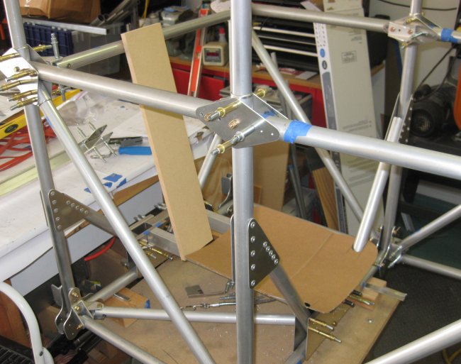
Passenger / forward cockpit seat mocked up.
4/7/12 - forward section
1/2 hr - upper firewall cross-beam. Filed on the gusset plates that go in either end of the cross beam to get them to sit flush inside the u-channel. The very edge of the gusset plates was riding against the radius inside the U. Got that done and initially trial-fit to the upper longerons.
4/8/12 - forward section
3/4 hr - making things fit. Pulled off the upper firewall cross-beam. Filed a little on the upper longerons - since the left side did slide into position, and the right side was a bit more snug, I figured just a little filing would do it - and it did. Both sides into position. Now, how to check for square across the front? I clamped a level across the forward frame of the center section, just above the lower tubes. Then measured from the level to the forward cross beam. 1/32" difference between the two sides. I had marked the right side as 1.5 mm short (a cutting error in the tube), but that side was the side that stuck out farther. Did not do any checking for left-to-right centering or level - either of those could affect the answer (tough to hit points in 3-d space!). So I will need to re-do this when I level the table and start from the fuselage assembly being mounted level axially and laterally. Then proceeded to check the plates halfway along the forward upper longeron tubes (pictured above). Removed the outer plates each side and drew a horizontal line along the longeron tubes (there was one there before from marking the hole location initially, but it was mostly wiped away by now). I put the plates back on, and with a few iterations of filing clearance in the shorter vertical tubes there, I was able to center up the upper longerons on the holes in the side gusset plate. Then I marked through the holes onto the upper longeron tube since the hole in the upper longeron tubes were nowhere to be seen. Turns out, each of these holes is off by 4 to 4.5mm - the plate is forward of the hole in the tube. I will re-check the dimensions here, but it may be the case that these holes would be better drilled in place rather than pre-drilled.
4/10/12 - forward section
1/2 hr - clecoed the forward set of diagonal tubes in place. Shaved edges on the gusset plates in the lower forward cross beam so they would fit flat to the sides of the bent up U channel (similar to the upper cross beam). Clecoed one of the FB22 U channel brackets to the bottom side of the upper cross beam, but with the cleco in there, can't get the diagonal tube inside as well. So can't tell if the pilot holes in the end of the tube are going to line up with the U bracket.
4/11/12 - forward section
1/2 hr - leveled it up front to back and left to right. Then shimmed the forward upper longerons to as level as I could get them with the inner & outer gusset plates clecoed to the 3 other tubes (not the longerons) so I could move the longerons up as needed to achieve level. Also checked the forward cross beam was level, so both of the longerons were shimmed to the same height, then drilled through the outer gusset plates. Pulled off the lower gusset plates and re-drew the tube centerlines on those, clecoed them back on, lined them up with the centerlines and drilled the other holes, locking those down. Now need to think about what the next move should be.
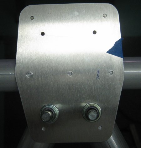
Side plates drilled and forward diagonals set in place.
Upper side plates drilled.
Lower side plates drilled.
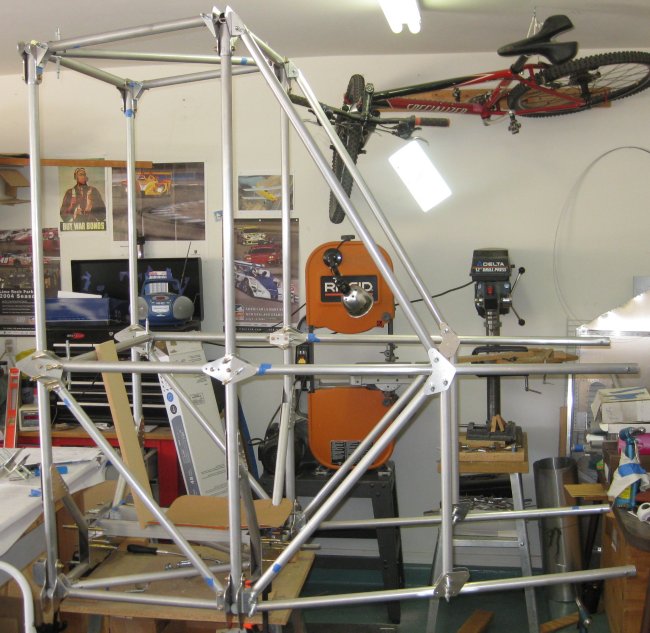
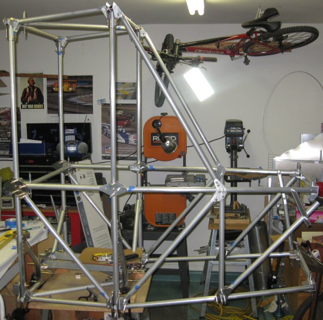
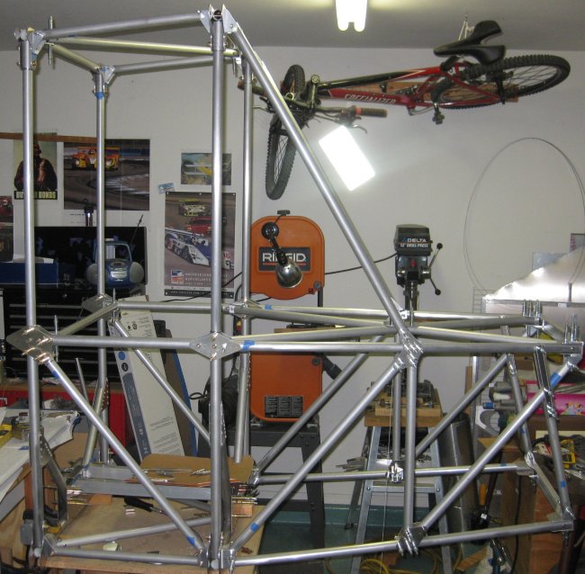
Forward looking aft - this will be reinforced with a bunch of diagonal tubes.
4/12/12 - forward section
1/2 hr - drilled the inboard sides of the plates pictured above, and finished drilling remaining holes in the outboard plates. Test fitted the U-channel brackets (FB23) that go on the inside of the upper and lower plates. In one view, the upper U-channel brackets are shown backwards from in 2 other views. I'm going with what the 2 consistent views show, which means these brackets (which are not symmetrical in side view) will be opposite directions between the ones on the upper and lower longerons. The lower longeron ones can only go one way because the hole spacing on the lower gusset plates is unequal. Test checking the tube FT26 which goes across these brackets, the tube is roughly 1/2 inch too long. On the plus side, I can cut the tube off including the pilot holes already drilled in it, drill new holes, and it will fit with no extra / unused holes. I believe the other diagonal tubes are pilot drilled in one end only, so if there is any length difference in those, it is taken up at assembly.
4/13/12 - forward section
1 hr - drilled upper firewall cross beam to the upper longerons. Drilled the outermost fastener to final size on the left side, allowing the FB23 U-channel bracket to be bolted on. Bolted that on. Looks like it covers up one of the rivet heads on lower side of the u-channel. I guess the simplest solution there is to install the rivet then file clearance into the bracket. Lined up the diagonal that goes in that U-channel bracket. Length seemed to be really good - not a lot of displacement to get both ends of the tube to line up. So clecoed that in. Then started fitting the upper "X" - starting with the forward triangle. These tubes need a lot of fishmouth to clear the upper longerons. But I got those two fitted, then could see that the joiner plate in the center of the X was not lining up with the cross tube. I had taped a string across the tube attach holes to indicate the axial position of the center plate in space. This is probably because the vertical gusset plates on each side were running about 4.5 mm forwards of the holes pre-drilled in the upper longeron tubes. Never did figure out why those were out of place, but too many other tubes fed into it (6 others) to change that. So I think the best solution is to re-make the U-channel brackets for the FT26 cross-tube such that the tube attach holes are ~5mm farther aft (will re-check with the string). Then clecoed on the FT28 tubes (the aft portion of the X), and these seemed WAY short. Then I realized I had clecoed in the ones for the lower X, which are shorter. Got the ones for the upper X, and it looks like these fit pretty well, so I think the X itself is in the right place.
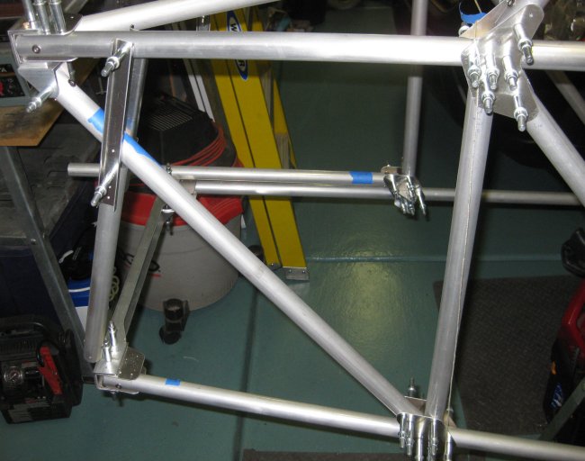
Diagonal tube going up to the left drilled in position after the upper cross bar was bolted on.
Aft is up in this photo. String does not line up with holes in central gusset plate (it should).
Similar to the photo 2 days ago, but with the upper X bracing going into position.
4/14/12 - forward section
1/2 hr - got the lower firewall cross beam so the pilot holes line up. This took some filing on the lower longeron tubes to flatten them a little, as well as a tiny bit more clean up on fitting the gusset plates inside the cross beam U channel. Now I think at least this part is ready for up-drilling to final size, so the FB23's can go on, so the lower side diagonals can go in. That would complete the side structure to pilot-size drilled.
4/16/12 - forward section
1/2 hr - drilled the other 3 corners of the firewall cross-beams to the longerons. Up-drilled the 3 U-channel brackets for these corners and got them bolted on. Lined up the diagonal tubes and got them clecoed in. With the lower to upper diagonals, this pushed the upper longerons up just a little, so when I went to cleco on the other diagonals that go to the forward ends of the lower longerons, those had to pull up a little as well. Will see if I can adjust the effective length of those lower-to-upper diagonals within the pilot holes (elongate the pilot holes) to take out the bend.
4/17/12 - forward section
1/4 hr - pulled the clecoes out of the diagonals. The lower-to-upper which were drilled slightly too long, I was able to relieve the stress by sliding the tube down a hair relative to the lower gusset plates and re-drill the holes. Only about half a hole-width off, and in up-drilling to final size, this completely disappears. Then for the upper-to-lower diagonals (3 pieces each - one tube and 2 small c-channel parts), these are off a further less-than 1/2 hole width off to relieve the bending on the lower longerons. This too will completely disappear in up-drilling, so the longerons will be diagonally braced unstressed and straight (at least in the up-down direction - will have to ensure the diagonals don't add any lateral pull in the structure.
4/18/12 - forward section
1/2 hr - up-drilled the longer diagonals at the bottom end to make the re-aligned pilot holes disappear. Then set up the shorter, 3-piece diagonals. Got the left one drilled into position. Filed the clearance on the right one, and got it drilled into position. I'm a little concerned that the lower RH engine mount point might be a hair low, but the crossed diagonals measured the same, so I wasn't really sure what to adjust. And if it is low, it's only by 1/16" or less, which is probably pretty good for this part of the structure. Anyway, easy enough to shim an engine on a mount to put the prop flange right where it should be.
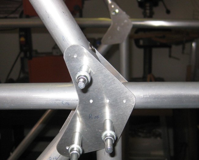
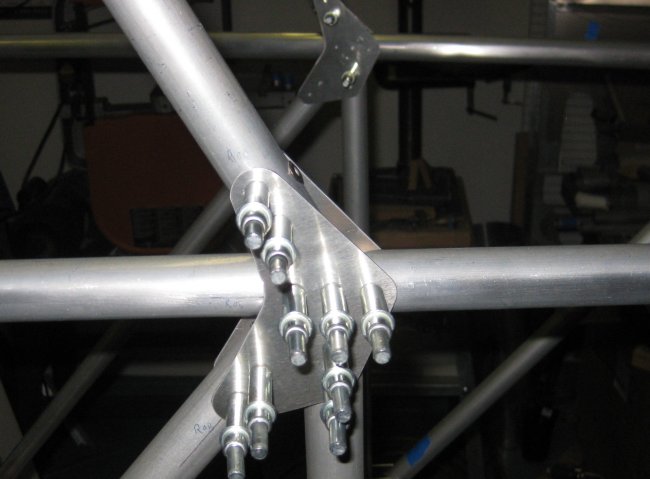
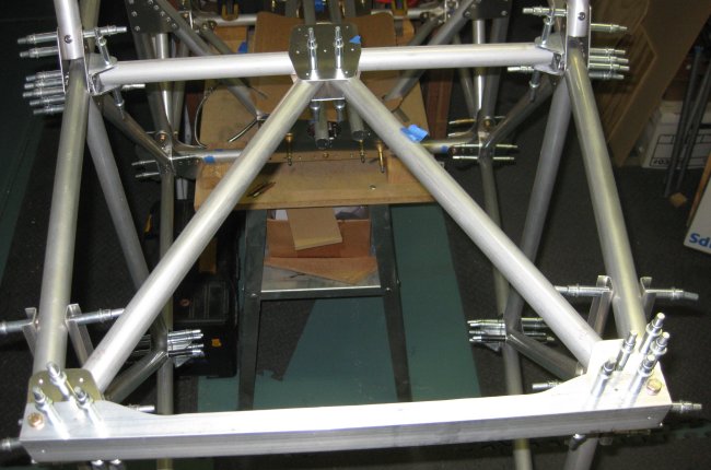
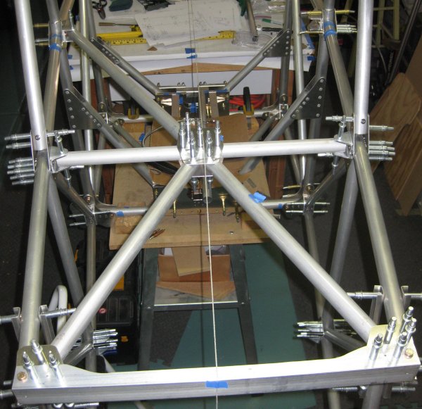
Forward diagonals all pilot drilled into position.
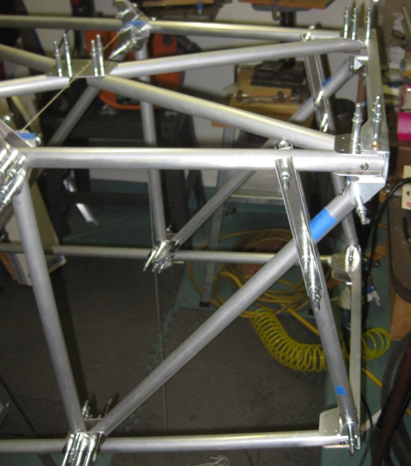
Forward diagonals.
From this angle, can really see the 3-piece forward diagonals.
4/19/12 - forward section
3/4 hr - filed clearance into the aft end of the tubes in the upper forward "triangle" of the upper X. This was needed to allow the lateral tube to clear. Could not place the lateral tube in there, though because the FB23 brackets placed it 7mm too far forwards. So brought some of the left over U channel inside and marked perimeter and hole locations for a pair of FB23 brackets 7mm offset from the print.
4/20/12 - forward section
1/4 hr - cut replacement FB23 brackets to length and drilled the holes. Deburred the holes, clecoed in place and checked the location with the string stretched across. Looks really good.
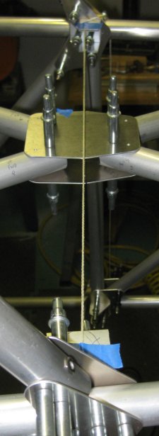
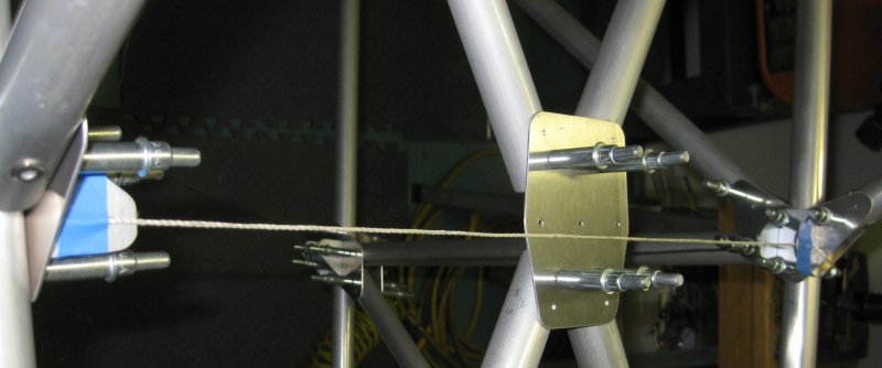
View across the string.
Trying to get close-up at the center gusset plate - camera isn't aligned exactly with the string and holes.
4/21/12 - forward section
1/4 hr - made the shaping cuts on the replacement FB23 brackets, sanded & scotchbrited these brackets.
1 hr - installed the replacement FB23 brackets. They both required a little clearance to the forward rivet - trick is to install the forward rivet before the bracket. I thought these might work with a bolt through the tube temporarily, but I'm not sure the inboard to outboard holes line up exactly. So rather than struggle with that, I just riveted the brackets onto the tube. I hope this doesn't trap something else, but the FT26 cross-tube could not go on with the brackets just clecoed because the clecoes would get in the way. Last item for now - clecoed the cross tube in place and the forward triangle of tubes. Looks like the center gusset plates will line up with the cross tube just right.
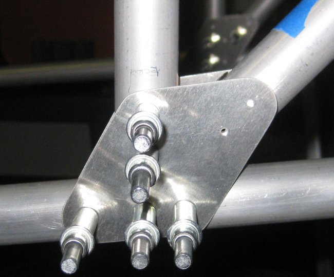
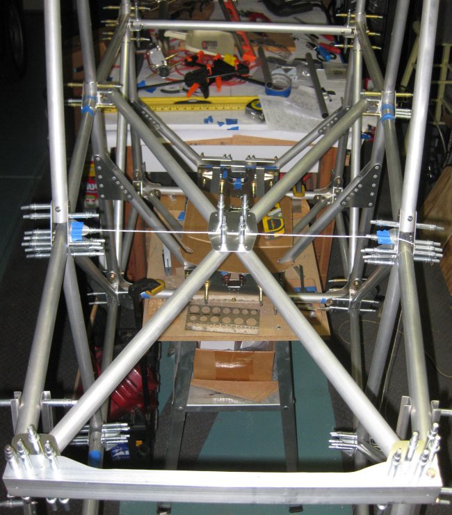
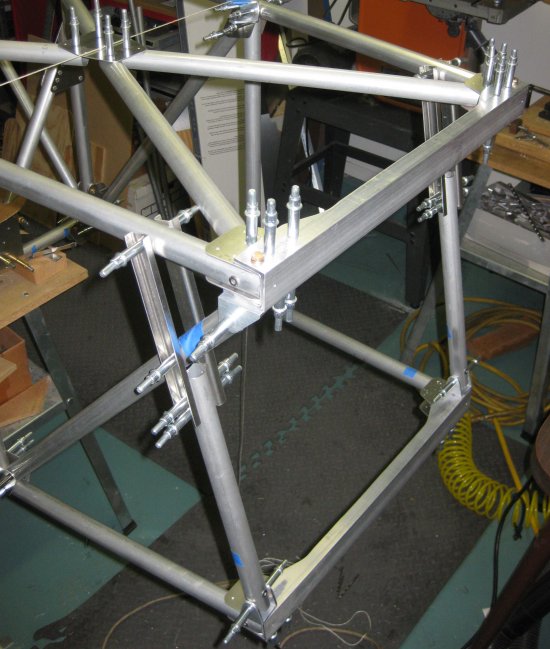
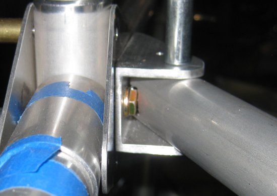
FT26 cross-tube in place.
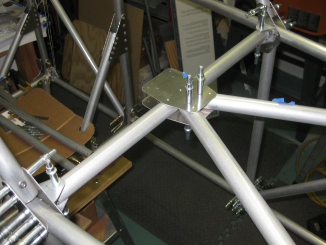
Trying to show the centerline drawn on the tube lined up in the pilot holes in the gusset plate. The re-made FB23 brackets position the tube right on.
Right side bracket riveted to the longeron. Small clearance for the forward rivet.
Left side bracket riveted to the longeron. Clearance for the forward rivet. Install forward rivets before FB23 brackets.
4/21/12 - forward section
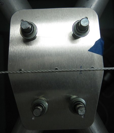
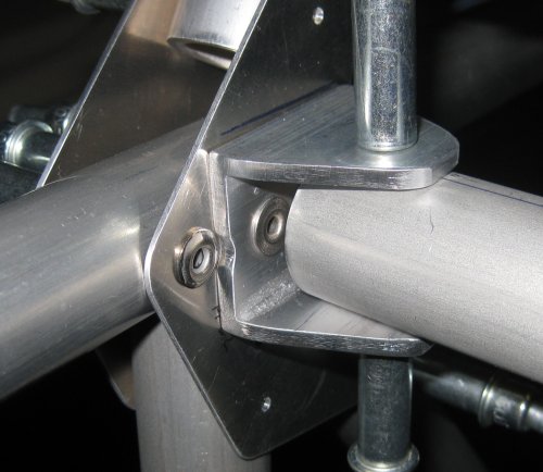
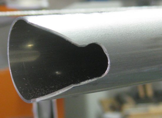
1/2 hr - fitted one of the rear diagonals in the upper X. This took quite a while because not only is there an angle to be cut into the aft end to clear the U bracket, but the cut must be extended forward up the tube some to clear the bolt head of the bolt securing the U bracket.
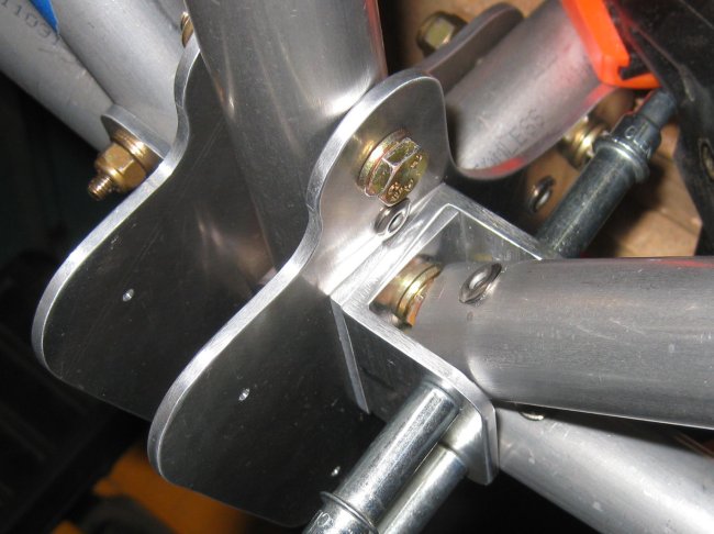
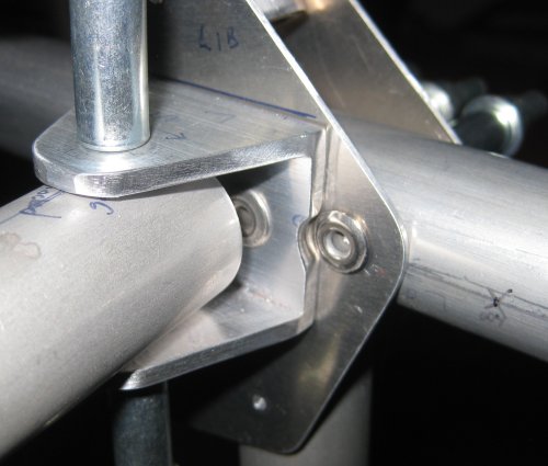
Diagonal tube of the "X" going in - upper left in this view.
The string on the centerline was exactly centered on the pilot hole in the central gusset plate. In this photo, the string is offset by the cleco, but that gusset plate is exactly centered.
Looking into the U channel bracket at the aft end of this tube - clearance for bolt head required.
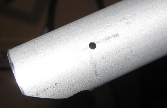
Looking down on the end of the tube - seems simple enough.
Looking across the tube, the simple cut is extended to clear the bolt head. Many iterations of checking fit and filing a little more.
4/22/12 - forward section
1/4 hr - fitted the other aft tube, completing the upper X. This didn't take nearly as long - maybe because I knew what to expect with shaping the clearance for the bolt head. On to the lower X.
End of this page. See Fuselage 5.
Click to join sherwoodbuilders