Sherwood Ranger - Fuselage - 5
*This web site is NOT owned or managed by G-TLAC. G-TLAC is not responsible for the content unless explicitly stated. See Disclaimer.
4/22/12 - forward section
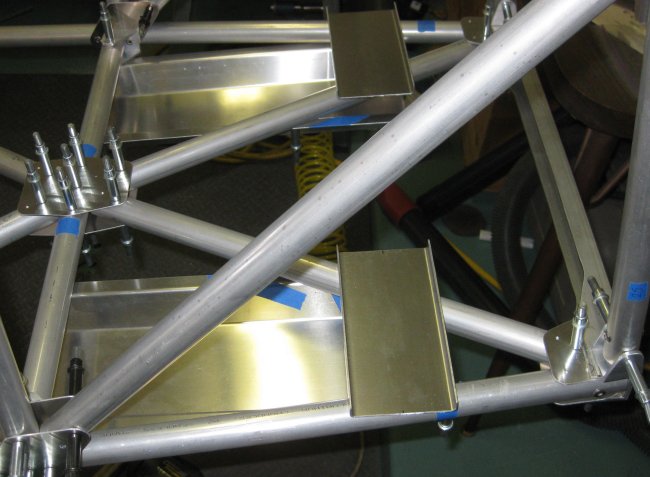
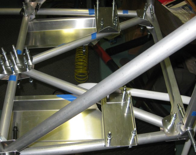
1/2 hr - fitted the forward 2 tubes of the lower X. There's a rounded notch at the outboard corner of each forward end to clear the lower longerons, then a flat slice off the inboard side of each aft end to allow the two tubes to get close enough to form the necessary triangle. Got the gusset plate fitted over the top, and the string between the two lateral tube brackets. Alignment looks much better than for this part of the upper X - maybe 1-2mm difference, which I should be able to make up in alignment of the pilot holes.
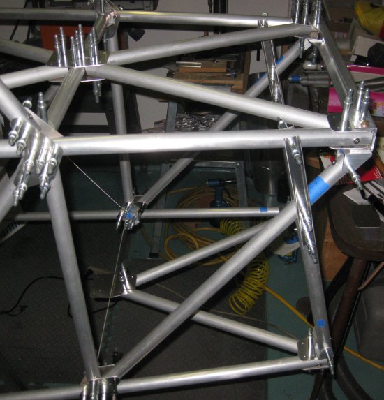
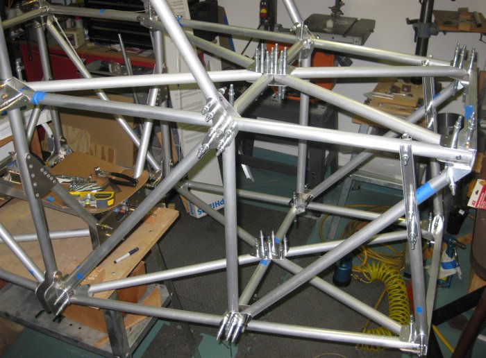
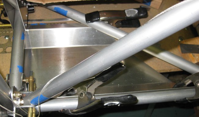
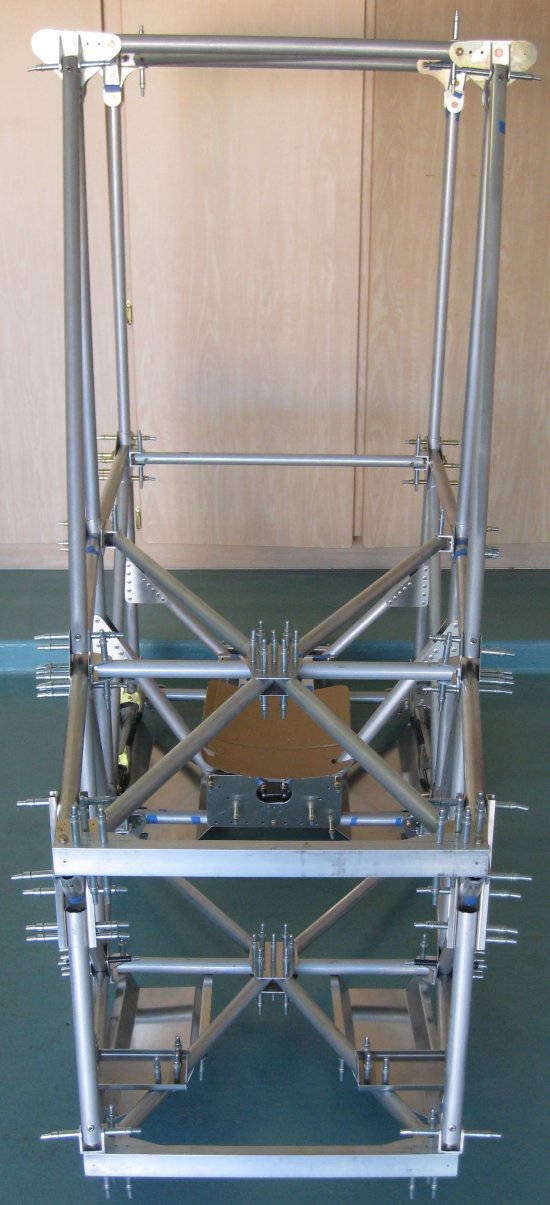
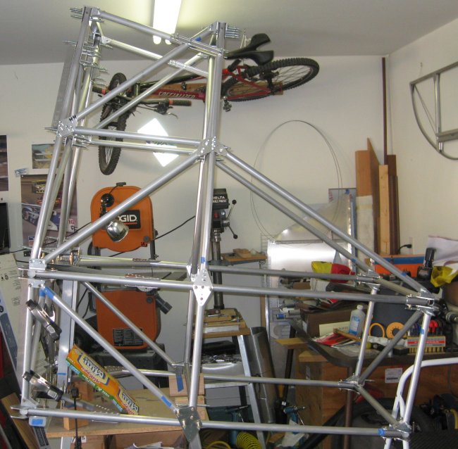
Upper X at least initially clecoed in place, forward triangle of the lower X going in.
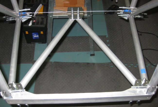
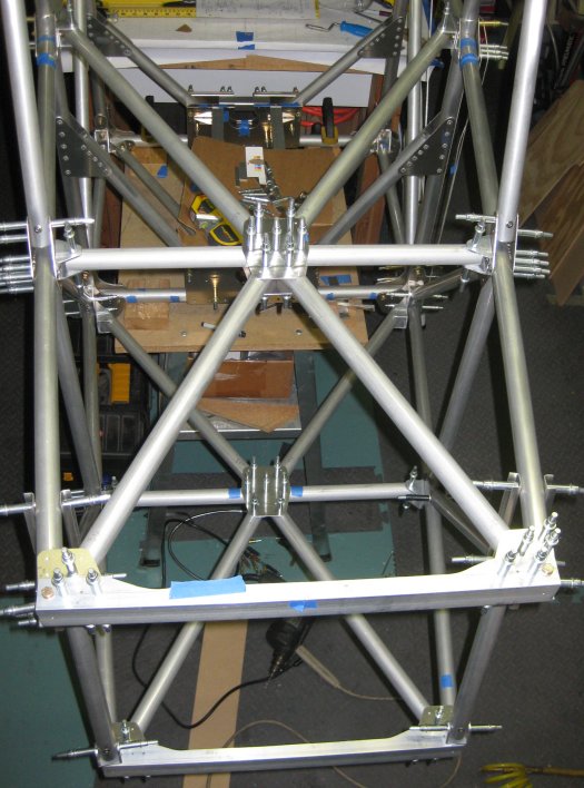
Forward triangle of lower X, with string across the FT26 tube brackets to compare alignment of brackets on lower longerons with the holes in the central gusset plate.
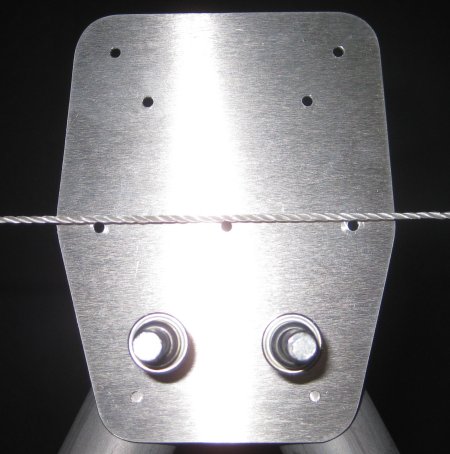
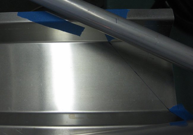
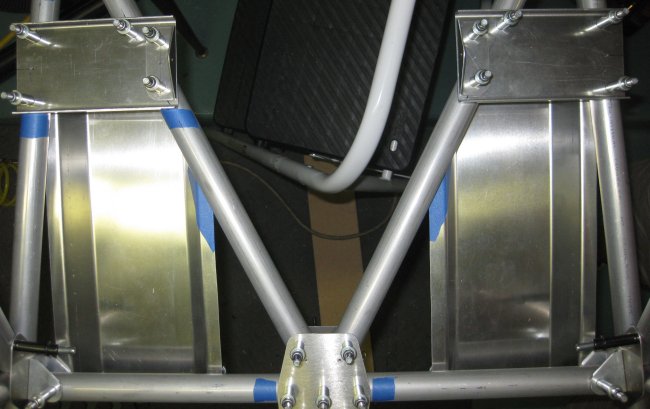
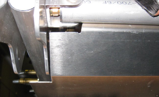
Close-up of alignment string with holes in central gusset plate.
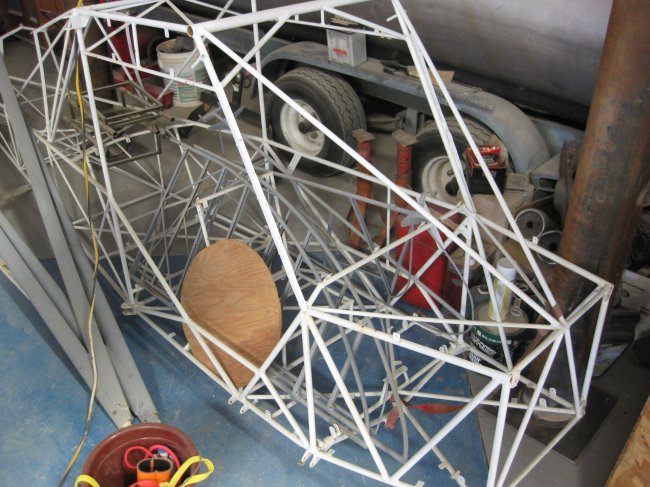
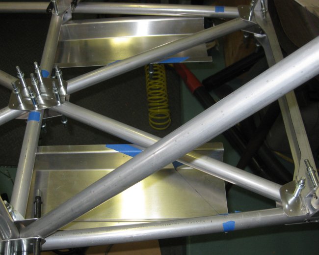
Seeing this little steel-tube-framed single-seater at the EAA meeting yesterday reminded me how beefy the 1" and 1.125" tubes on this Sherwood fuselage will look to people familiar with welded steel.
4/24/12 - forward section
1/2 hr - got the lower FT26 attach brackets riveted to the lower longeron. Same issue as with the upper X cross-beam - can't fit the tube with the brackets clecoed in place. They need to be riveted.
4/25/12 - forward section
1/2 hr - got the lower FT26 trimmed to length and drilled into position. The two tubes of the forward triangle fit just fine to this tube w/o any clearance needing to be filed. Maybe this lower X is turning out to print. Not sure what happened on the upper X, but it might be worth not drilling the mid pilot holes in the upper longeron tubes - and also not pilot drilling both ends of the FT26's. Fortunately, my FT26's turned out short enough that the pilot holes on one end were completely trimmed off (both upper and lower). Found the FB61's for the aft tubes of the lower X (that took a little while). Got those clecoed on - need the saddle spacers here, but since they sit exactly .125 off the tubes, I may just make some temporary spacers from stock until I get the saddles made. Quickly placed the lower aft X tubes (FT28) in place and saw that they need a little clearancing at both the forward and aft ends of the tubes. Save that for another day.
4/26/12 - forward section
1/2 hr - fitted and pilot drilled the lower aft X tubes. I thought these might need temp spacers, but clecoed onto the U channel brackets with deep reach clecoes, they seemed to sit just fine. Now it's mostly pilot drilling all the holes I didn't get to yet and drilling it all to final size.
4/28/12 - forward section
1/2 hr - passenger / forward foot rests. Marked aft corner holes for drilling. First one I did (right side), I clecoed the outboard corner through the U-channel bracket hole for the cross tube (per the print), then, using an extended centerline drawn on the cross-tube, lined up the inboard pilot hole with the centerline and drilled. Then found it was a stretch to get the forward outboard corner lined up. For the second one, I marked/drilled the 2 aft and forward outboard holes (all 7mm in from the corner), clecoed the outboard aft corner through the u-channel bracket, lined up the forward outboard corner with the centerline of that tube (by TLAR - That Looks About Right method). Drilled forward outboard corner, then drilled aft inboard corner where it fell. Now, lining up the inboard forward corners is tricky. So I sighted from above, and placed masking tape exactly either side of the tube on the foot rest part. Then I took the part down. Turns out, I did a pretty good job, as the two pieces of tape measured 1 inch apart. Find centerline between the two pieces of tape, then measure 7mm in from the edge of the part. Where 7mm crosses the centerline between the tapes, that's where the hole goes. Marked, center punched, and drilled that hole on the drill press. Then clecoed the part back in place, and drilled through the part into the tube from below. Marking where to cut the forward inboard corner off of the foot rest - print says 10mm forward of the inboard hole. I went 1/2". Then "straight line" across to the bend of the outboard flange. Didn't cut these yet. Got out the u-channel pieces that support the rudder pedal mount brackets - more "floating in space" geometry and holes to locate. I will figure that out later.
Trying to show the masking tape laid on the foot rest part by sighting over the tube from above. Did this on both sides of the tube, then located the center line between the tapes, and where that intersected with 7mm in from the edge of the part - located hole there.
Both foot rests drilled into position.
Approximate location for the rudder pedal support brackets.
4/28/12 - forward section
1/4 hr - rudder pedal support bracket, right side. The geometry defining the hole locations for these brackets is not very complete on the print. In fact, only one hole, the aft outboard, is actually defined. And the geometry defining the bracket location on the airframe is there, but not directly usable - the fore-aft position is defined from the FT26 cross-tube mount bracket hole to the centerline of the rudder pedal support bracket. If you mark this station on the airframe, you can't see it with the bracket in place - so that's not usable as-provided. Have to back out 1/2 the width of the bracket, and subtract this from the station marked on the tube, so you can see where the aft edge of the bracket goes.
On the inboard edge of the bracket, this same distance must be measured using the centerline of the FT26 cross-tube, since the lower longeron angles both inwards and upwards at this part of the airframe. (making the bracket square to the longeron would make it angled to the airframe). So with a centerline drawn by eye on top of the lower longeron, and the lower aft hole in the bracket located and pilot drilled, and using the marks drawn to indicate where the aft edge of the bracket should go, I drilled the first hole.
Then I clecoed it in place, and eyeballed where the forward outboard hole would go (along a line drawn inside the bracket, 28mm forward of the bracket center line. Then connected the dots - forward hole location estimated with aft hole location actually drilled - to locate the hole location on the bracket center line. Marked, center punched, and drilled those two holes on the drill press. Then clecoed the bracket back in place by the aft outboard hole. Lined it up fore-aft on the inboard tube with the mark on that tube previously made, and spring-clamped the bracket to the inboard tube. Then drilled the forward two holes on the outboard side through the bracket into the lower longeon tube. Oh, I used the right-angle drill adapter for all 3 of these outboard holes so as to not have to un-cleco the diagonal in the side structure to allow clearance for the drill motor.
Then, I eyeballed the location of the holes on the inboard tube by sighting down on the bracket from above. Marked the hole locations 28 mm from the center line. But wait! The aft hole is NOT 28 mm from the bracket center - it is only 20mm because that hole is also used to attach the rudder pedal mounting bracket. Of course, I marked, punched, and drilled the hole at 28 mm, clecoed the support bracket in place on the structure and drilled through to the lower X tube. So now it has an extra hole. Not a big deal. I re-drilled the additional hole at 20mm offset, clecoed the rudder pedal support bracket, and the rudder pedal attach bracket to the structure.
A lot of words for not a lot of time. But if all this was in CAD, I don't see why they couldn't add a couple more dimensions to the figures to define a few more of the hole locations (and bracket overall location relative to features you can SEE before drilling holes through it). I would add the axial location of the AFT EDGE of the bracket on the two lower tubes, as well as calling out that aft inboard hole location is NOT 28mm from the bracket centerline, but 20mm. Oh, and the bracket overall seems too wide (protrudes too much in the inboard direction). I will figure that out later.
5/1/12 - forward section
1 1/4 hr - got the left side rudder pedal support bracket drilled into position. Much easier with knowing how things are going to line up. Got the "sight it, mark it, drill it, then check it to the tube centerline to see how you did" holes all pretty much right on. Drilled the rudder pedal mount brackets (inboards only) drilled to the support brackets. With these lined up, marked the support brackets to trim the excess off the inboard sides. Trimmed the foot rests to size, sanded and scotchbrited the cut edges. Started working on the left side pilot's foot rest. Cut the forward corner on the band saw to clear the brackets on the forward fuselage frame. Found the cuts did not position it quite forward enough, so trimmed a little with a hand shear. Smoothed these edges. Spring clamped it into place and saw the diagonal line I had laid out left too much material, so adjusted the line a little and cut the part on the band saw. Smoothed that edge. That's enough for now.
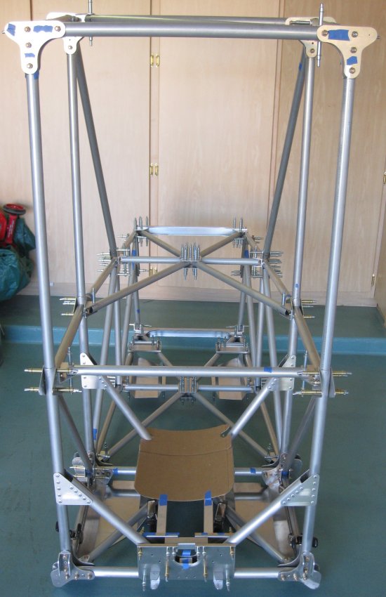
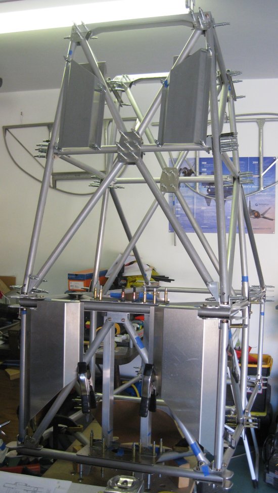
Forward foot rests, rudder pedal support, and inboard rudder pedal attach brackets. All pilot drilled and trimmed to size.
Looking straight down from above.
View as the front seater might see it. Shows the angled forward edge of the foot rests.
Left side pilot's foot rest. Forward is to the left.
Forward outboard corner of the pilot's foot rest, showing the stepped cut needed to clear the fuselage frame structure.
5/2/12 - forward section
1/4 hr - cut the RH pilot foot rest to shape. Smoothed edges.
Right side view.
Right side view, camera a little higher.

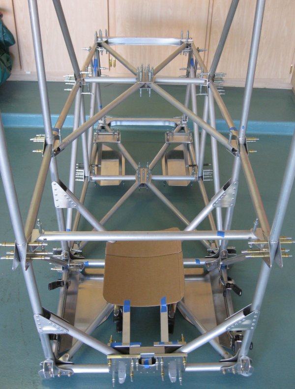
Forward looking aft.
Forward looking aft, camera a little higher.
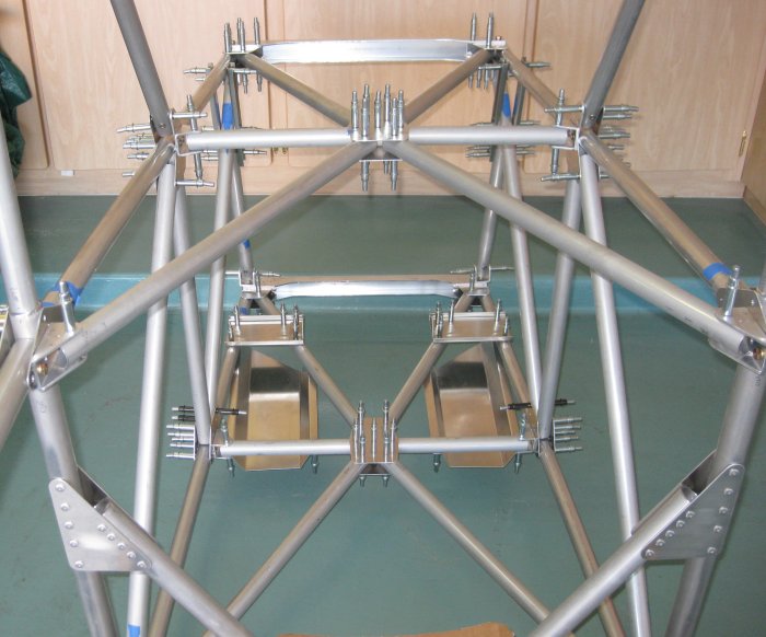
Aft looking forwards.
Approximately the pilot's view.
What the front-seat passenger sees.
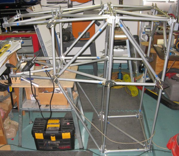
Set it in a vertical up-line on the table.
Looking up through the bottom. Idea here is to access the pilot's foot rests for drilling.
5/3/12 - pilot foot rests
1/2 hr - laid out and drilled 4 of the 5 holes in the LH pilot's foot rest. That would be the forward inboard hole, set at 7mm in and back from the corner of the part, and I laid out the 3 holes along the outboard side at 10mm in from the edge of the part, 3/4" from each end, then the 3rd hole centered between the two near each end of the part. The print does not specify where the 3 holes along the outboard side go, so TLAR (that looks about right). I marked the center line on the bottom of the forward frame tube by measuring between the gear/wing attach plates at the outboard end and using a small square off the center plate, since it is perpendicular to where the pilot's foot rest attaches. Then I pulled the FT8 (lower longeron) - but to pull that, had to pull the triangulation tube on the bottom of the center box (FT10?). Marked a tube centerline between the bolt holes on the FT8 - this defines the height of the attach points for the outboard side of the foot rest. Then spring clamped the foot rest into position and drilled through the forward frame - establishing the inboard forward attach point for the entire part. Enough for today.
5/4/12 - pilot foot rests
1/2 hr - got the rest of the pilot holes drilled for the LH foot rest. Did the aft outboard hole next (diagonally opposite from the hole from yesterday). Since this gets into the narrow end of the triangle formed by the FT10's, I held the foot rest in position over the centerline marked in the FT8 and marked the hole location with a pen. Then I pulled off the foot rest, pulled the FT10 tube to pull the FT8 tube (if you temporarily reverse the direction of the attach bolt on the FT8 from inboard to outboard to outboard to inboard, the FT8 can go on & off w/o touching the FT10).
Drilled the marked hole location on the FT8 on the drill press - I don't prefer doing this, but I couldn't see a way to drill it in place (there may be a way). Put the FT8 back on, the foot rest back on, and that aft outboard corner is so tight a normal cleco won't go in there, so I used a stubby threaded drill bit (~1/2" long) in that hole to align the parts, and a spring clamp next to that to hold them together. Then lined up the middle hole and marked that with the sharpie. Took it all apart again, drilled the center hole on the drill press, put it all back together, and the forward hole was only slightly off of the center line drawn on the tube (as viewed in a mirror, of course - this part is NOT designed for obvious installation!).
So I leaned on the part a little to bring the pilot hole onto the marked centerline - now, how to hold that, hold the right-angle attachment on the drill, and pull the trigger on the drill to make the hole? After thinking on that for a minute, contemplating just drilling the hole where it fell (off the centerline) - decided it would probably stay in place with a couple of spring clamps. So held it to the centerline, checked with the mirror, and added spring clamps. Then with both hands available, drilled the hole. Clecoed the mid and forward outboard holes (the aft one still has that little drill bit & spring clamp).
Then extended the centerline I had drawn on the bottom of the FT10 (you did catch that I marked a centerline on that one as well?) - then extended that centerline onto the foot rest. Where that tube centerline intersected 7mm in from the edge of the part - marked that spot for the final hole. Drilled that. That's one foot rest in place. I wouldn't like to have worked this with the airframe sitting any other way (but pointed straight up at the ceiling). Lots of words for drilling 4 holes...
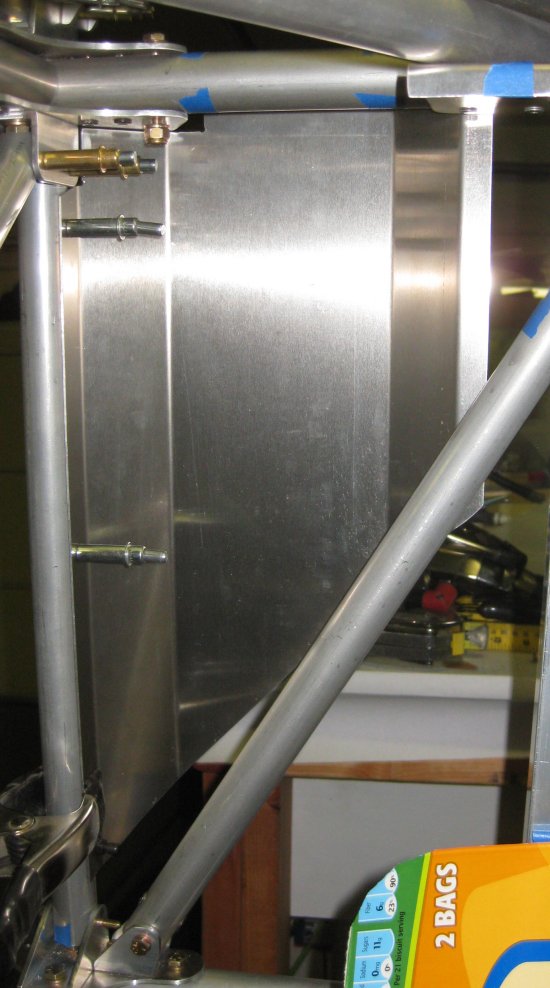
View inboard looking "down". Airplane forward is up in this photo. The tightest hole is lower left - not even a cleco fits there. How to rivet?
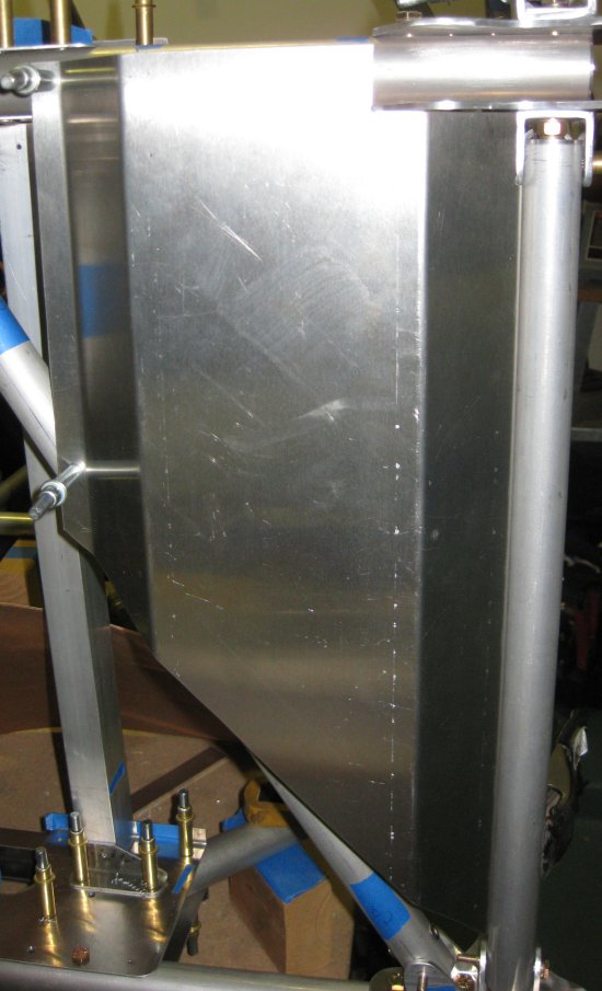
View bottom looking "up". Airplane forward is up in this photo. Left side of the view - upper hole is the first one drilled, the one on the diagonal tube is the last.
5/5/12 - pilot foot rest
1/2 hr - got the RH pilot's foot rest pilot drilled into position. Looks like it took about 1/2 the time on this second one.
5/7/12 - pilot foot rest
1/2 hr - got the 3 holes on the lower longeron drilled to final size. Then proceeded to install the longeron back end forwards because the hole pattern is symmetrical and I had markings on the tube for the wrong end forwards. Don't know if I got the tube turned around at some point, or got turned around when I marked the tube. But it doesn't work backwards because the foot rest is offset about 1/2" from the tube center. So re-marked it with the now-needed end forwards. Got that put back in place. You know, it's getting frustrating pulling bolts in and out, and as I put the first bolt in the second time, I was thinking - I don't know why I'm struggling so much to get the threads all the way back through, because I'm just going to pull this out in a minute for something else anyway - well, I guessed the wrong bolt, but I did pull the tube back out almost instantly to turn it around. Frustrating. Anyway, that Budd Davisson article (SA, this month) about keeping a notebook to plan work on the airplane when you can't get out there - the flip side of that is it's just as well that I don't have hours to work on this on end, as it would probably be too frustrating, and I would be better off to walk away anyway.
5/8/12 - pilot foot rest
1/4 hr - wanted something easy. Drilled the 4 holes on the bottom of the foot rests to final size. Pulled off the LH foot rest to final size drill the 3 holes on that lower longeron tube, but stopped there.
5/9/12 - pilot foot rest
1/2 hr - drilled the 3 holes on the lower longeron tube to final size. Then cleaned up the work table - in part because tools just gather, but also to find the 1" tube 90-degree marking jig. I'm going to add rivets to the inserts in the FT8's, because the inserts keep floating around on their own, and a little extra strength here (having the insert contribute to axial loads, not just tube crushing load) shouldn't hurt.
5/12/12 - pilot foot rest / lower longeron tubes
1/2 hr - drilled the FT8 lower longeron tubes for rivets at the insert locations. This is not shown on the print (these inserts are intended to be "loose" for crush-prevention only), but the inserts kept sliding around in the tube, and I felt that working them back into position would have the effect of expanding the through hole. The inserts are 30mm long, so I located the rivet holes at 15mm from the tube end. Also may do this for the other loose-insert tubes.
1 hr - drilled the forward seat support rails to final size, except under the forward brackets since things were not positioned to get to those very well. Turned the whole structure back upright and started drilling the left side of the forward structure to final size.
5/13/12 - forward structure
1/2 hr - completed up-drilling the left outboard side of the forward structure (from center box to firewall) to final size. Started looking at the 3/16 cleco situation - have about 15 on the left outboard side, still have quite a few on the center box structure, and have about 30 available for use. This will easily cover the right outboard side, and probably either the upper or lower X, but probably not both. Will need to figure out a strategy to get some of this riveted/bolted.
5/14/12 - forward structure
1/2 hr - drilled right-hand outboard side of the forward structure to final size. About out of 3/16 clecoes. Need to figure out what can be finished off to free up some clecoes to work the drilling of the interior of the forward structure.
5/15/12 - forward structure
1/2 hr - completed a few remaining pilot size holes in the upper and lower X's. Removed these to make way for drilling the inside of the forward structure. Got some of that drilled up to 5/32 size. Found a couple more "how the heck do I install this" rivet locations - just above and below the u-channel brackets for the FT26 cross-tubes (center of the X's). Recall the u-channel brackets had to be riveted in place to fit the cross tubes - well the vertical tube between the upper and lower longerons has a rivet at each end of it that is very close to the u-channel brackets. Should be able to install these rivets with an angled extension on the rivet puller tip, if needed.
5/17/12 - forward structure
1 hr - pulled off parts as required to get the upper and lower firewall cross beams off. Drilled the engine mount bolt holes. Test fit the anti-rotation inserts for the firewall bolts (notch in the solid tube insert engages the hex on the engine mount bolt heads, allowing them to be torqued without access to the heads). The lower ones fit really nice. Should be able to assemble these with little difficulty. The upper ones - the holes in the tubes were not exactly opposed, so I will need to file the inserts a little to open up the through holes. Should not be a problem at all, since all these do is allow for torquing the bolts at engine mount installation.
5/20/12 - forward structure
1/2 hr - a couple of days off - seems like I'm doing something way out of order with fitting those engine mount bolts. I would recommend doing these sooner, at least as far as fitting the end-of-tube inserts. Reassembled the upper and lower cross beams, as well as the X's, upper and lower, in order to final size drill the holes in the cross beams and X's. I don't have nearly enough clecoes to cover this, so maybe will order some more, or think about what else could be final fastened / riveted to free up some clecoes.
5/24/12 - overall items
No time, just some ideas. Counted up the silver (3/32) clecoes currently still on the forward structure in order to approximate how many 3/16 clecoes it might be good to have before proceeding with drilling all that to final size. Impressively, it's in the high 60's. Have 20-30 3/16 clecoes loose at this point, so it would probably be good to order another 50 or so before proceeding.
Also took some time to scale off some dimensions of the cockpit area - I may fab that of metal rather than use the fiberglass from G-TLAC. This resolves a couple of issues - the fiberglass requires that quite a few fasteners at the top of the fuselage structure remain temporary such that the 6 tubes up to the upper wing can be removed to allow the fiberglass to be positioned over the fuselage, then the 6 tubes re-installed. The number of fasteners that appear to need to remain temporary is driving me nuts - if everything is temporary, when can anything be finalized? I like to finally install stuff and move on. With multiple pieces of sheet metal forming the cockpit surrounds, the underlying tube structure can remain in place while metal is slipped in around them. This also would avoid shipping a large crate containing a couple of pounds of very expensive molded fiberglass halfway around the globe.
Yet another problem solved by making my own is that if the contour of the upper deck needs to be tweaked to clear a locally sourced (or fabbed) fuel tank, I can do that. Yet another part I was researching was theoretically usable automotive fuel tanks. Probably a bit of a weight hit here, but much lower cost than the G-TLAC part (in the mid $700 range, last I checked). Similar fuel capacity can be had from two 8" diameter x 30" long dune buggy tanks, at 6.5 gallons each, available locally for ~$150 each. (There is 31.5" from firewall to forward instrument panel, so there would not be instruments in the center of that panel if the tank was right there, but there isn't going to be much instrumentation up there in any case.) Or I will see what it takes to fab up my own from some riveted Al or epoxy / fiberglass composite. Either way, it's lower cost, and again avoids shipping a somewhat less large crate halfway around the world. I guess I'm learning what the rest of the world thinks about when plans-building a U.S.-sourced design...
6/3/12 - forward section
1/2 hr - getting back into it after some days away. Drilled the upper sides of the upper and lower firewall cross beams to final size. At the upper side of the lower beam, there is one of the gusset plate fasteners on each side that will interfere with the U bracket. (Same thing happens on the lower side of the upper cross beam, but I'm not there yet.) In looking at the photos provided by G-TLAC, it looks like the solution used on an old/prototype airframe was to use a countersunk rivet here, rather than clearancing the bracket around a protruding rivet head. Seems simple enough.
6/4/12 - forward section
1/2 hr - drilled some more holes to final size. Running out of 3/16 clecoes. I thought I might get some final fasteners in and not need so many, but gave in and ordered some more. That will bring it to something around 200 in this size. I have more in the other sizes from the Sonex build, but to start this one, probably could get away with 200+ in the 3/32 size, 100 or less in the 1/8 and 5/32 sizes. Less in the 1/8 and 5/32 because they are only in place for a few minutes at a time, as intermediate steps from the small pilot holes to the final size holes. And my guess is there won't be nearly this many needed for the wings.
6/5/12 - forward section
1/4 hr - turned the assembly upside-down to drill the underside holes that would be difficult to reach otherwise. Had to add a couple more 3/16 clecoes to the assembly for stability, and that uses all that I have for now. Drilled some of the holes through which had not been even pilot-size drilled, then drilled some to #30. Didn't feel like rotating the clecoes because it's hot out there and with the assembly upside down, it's very difficult to walk around. Need to see if I can move it around a little.
Inverted fuselage to drill the lower fastener locations.
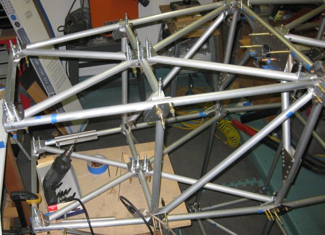
All the clecoes on top of the structure in this area are fastener locations to be drilled to final size with the structure inverted. Also will final size drill the front seat foot rests (not shown).
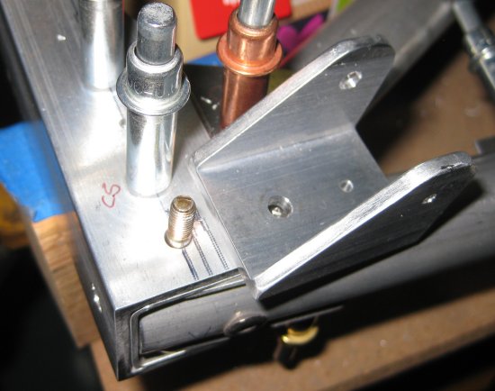
The cleco next to the CS (CounterSunk) marking is where the countersunk-head rivet will be used to allow the u-channel bracket to sit flat over the top of the rivet location.
Click to join sherwoodbuilders