Sherwood Ranger - Fuselage - 6
*This web site is NOT owned or managed by G-TLAC. G-TLAC is not responsible for the content unless explicitly stated. See Disclaimer.
6/18/12 - forward section
1/2 hr - drilled some more on the structure while inverted. Worked out that I have 5/32 countersunk head rivets, so set up the microstop countersink for these and drilled the two under the upper firewall cross beam. This is to recess the rivet head where the u-channel bracket sits over the top of it. Much easier than filing a clearance into the u-channel, and it maintains the integrity of the u-channel, not that these would be challenged by a little clearance for a rivet head.
Showing hole location where countersunk rivet will be used.
Countersunk rivet in position. U-channel bracket mounts on the bolt, and overlaps the rivet.
6/19 - 6/20/12 - forward section
1/2 hr - drilled the last few holes I could get to with it bottom side up. Turned it over. Started re-clecoing in a couple of the forward diagonal tubes that I had out to drill other locations. Seems like forever, but I'm starting to nearly see the end of up-sizing the holes in this forward section.
6/23/12 - forward section
1 hr - finally got a solid hour before the kids got up. Drilled all the holes to final size on the right side, less one (that I will get to when I un-cleco surrounding tubes). Even with all the top holes done, all the bottom holes done, and all the outer side holes done, there was still a good number of holes on the inside of the structure. On the plus side, this design secures both sides of the tubes (not only gussets on the outside). I expect about as much work remaining to finish off the left side holes. Still need to get the saddles at the lower aft corners and get those drilled in, then it can start to go together for the final time.
6/24/12 - forward section
1/2 hr - drilling the internal holes on the left side to final size. Only a few more to go. Went a little faster than the other side - probably due to some familiarity with what needed to be done.
6/26/12 - forward section
1/2 hr - finished drilling the internally-located holes on the left side. Took longer than I thought. There was 1 hole that I missed earlier that required some adjacent tubes to be pulled out to access, and I had to remove even more tubes to access 2 other holes (1 right, 1 left) that I had intentionally been holding off from completing because I knew these would need a lot of tubes taken out of the way. So in the end, the left-side tubes took about as long as the right side.
July 2012 - not much progress
Between a business trip, a family vacation, other family being in town for a week beyond that, and going to Oshkosh, no much progress for the past few weeks.
7/15/12 - forward section
1 3/4 hr - deburring. Pulled off the upper firewall cross beam and the various brackets and gussets in this area. Deburred all this, plus the u-channels that form the upper end of the forward side diagonal tubes. A good bit of this time was filing the engine mount bolt retainer tube inserts - the lower pair of these fit right in, but for the upper pair, the bolt hole through the insert was offset slightly in each one. So had to buy some tiny needle files from Harbor Freight to file the inside of a 3/16" bolt hole. These holes being opened does not matter at all, as the function of the insert is to hold the engine mount bolt heads for tightening. Once torqued, the insert is just along for the ride. And even with the hole slightly opened, there's still plenty of meat in the insert to hold against the motor mount installation torque.
7/17/12 - forward section
1/4 hr - pulled off and deburred a couple more tubes. Couple of tubes each day, and eventually it all gets done...
7/19/12 - forward section
1/4 hr - more disassemble and debur - couple more parts.
7/21/12 - forward section
1 hr - drilled the forward rudder pedal support plates to final size on the tubes. Probably had not done this before due to a lack of clecoes and other tubes in the area. Just easier now with all of the forward side tubes out. Found 2 holes that had not been brought to final size on upper aft diagonal - so used the 12" 1/8 dia drill and then the right angle drill to get those. May have held off on those because they needed the right angle drill and just forgot to get them when I had the RA drill attached to the drill motor. Deburred stuff as I went. Finished deburring the lower firewall cross beam and its related doublers / gussets. Clecoed that together on its own so the parts wouldn't get mixed up / separated.
8/1/12 - forward section
1/4 hr - removed and deburred several more tubes.
8/2/12 - progress lacking
Oshkosh � prep, trip, and unpack / digest info collected is taking the better part of 3 weeks. Though no progress being documented here does not mean there is no progress. I found multiple sources for a certain type of part (that the plans call out as custom-machined) that will knock maybe a dozen parts off my �total parts needed for the project� list. Not a huge quantity, but better than nothing. And since I can order them off-the-shelf, it�s that much less that will need to be custom machined. Another area I researched at Oshkosh was rudder pedals. From what I saw / photographed there, I have come up with a design that can be fabbed from some readily available aluminum stock that will be slightly lighter weight than the plans-defined welded-steel configuration. This design is also readily fabbed by me, and keeps me out of having to find out how much custom weld jobs cost (as well as eliminating some related custom-machined parts). Another area I looked at, but haven�t detail designed yet, is the control stick connection � particularly the stick connections for the elevator control. I believe I can eliminate yet more custom-machined parts in that area, though the AN-hardware I identified to achieve the same purpose may not end up costing that much less. (Though this may present an opportunity for the factory to simplify what they machine for their kit.) My concept configuration in this area may be easier to assemble, however.
8/4/12 - forward section
1 1/4 hr - more tube disassembly and deburring as I went. Had to remake the .062 gusset plates at the lower end of the diagonal tubes that come off the upper wing spar to get the 1/8" rivet hole positions better located on these plates. I think a combination of little things added up right in this corner. At this point, have nearly all of the forward structure off and deburred.
1/4 hr - attempted to finish off some drilling for the gusset plates. Got the right side done - all lines up, no problem. Left side, the hole that needs to line up because there is a bolt through the end of the tube I don't think lines up enough. Now thinking about what all needs to be remade / done over to make this work.
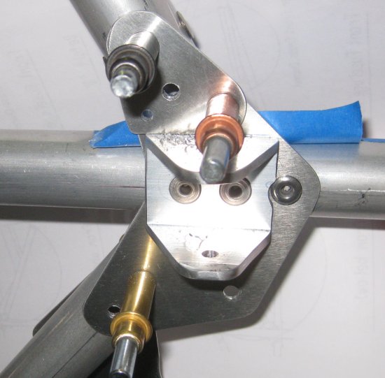
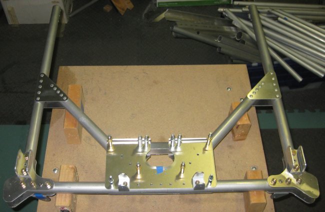
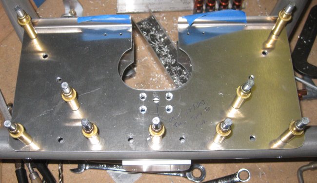
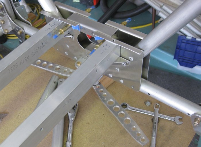
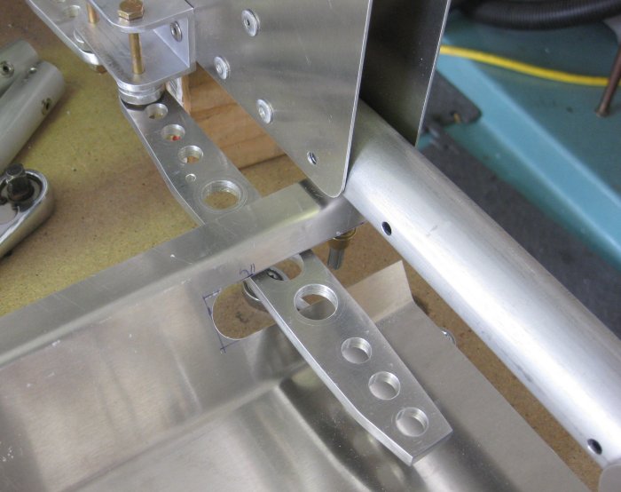
Right side, inboard looking outboard, forward to the left. This is the gusset plate that I re-made to reposition the smaller holes (copper cleco and the lower right-hand corner of the part). That's a quarter-inch bolt going through that largest hole. Blue tape is in there to prevent chips getting between the horizontal tube and the plate that is riveted on. This plate needed to be riveted on because clecoes in those rivet holes would have got in the way of fitting the cross-tube that goes in the u-channel bracket.
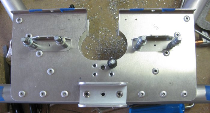
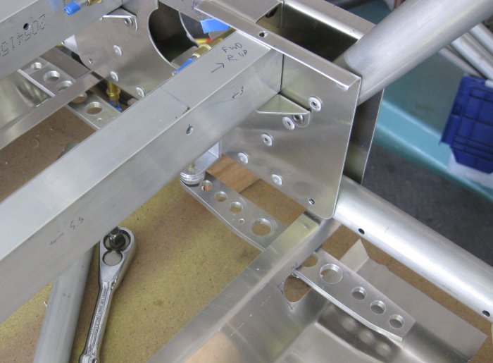
Right side, outboard looking inboard, forward to the right.
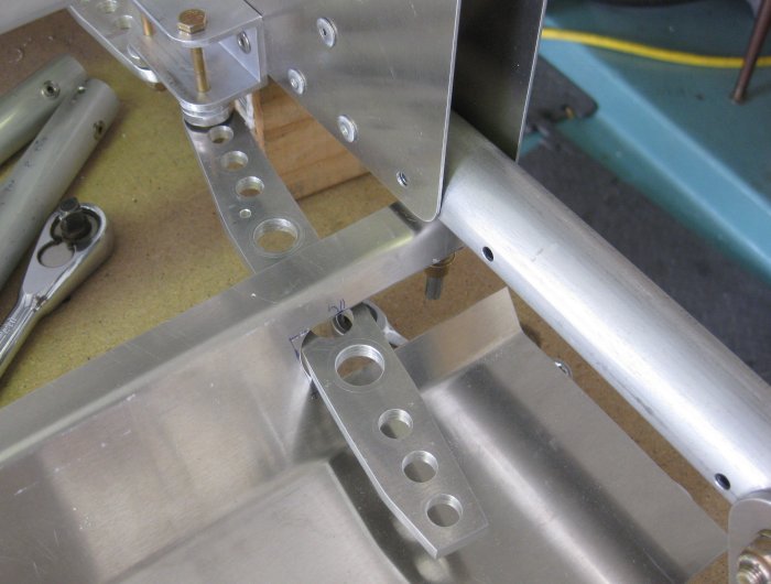
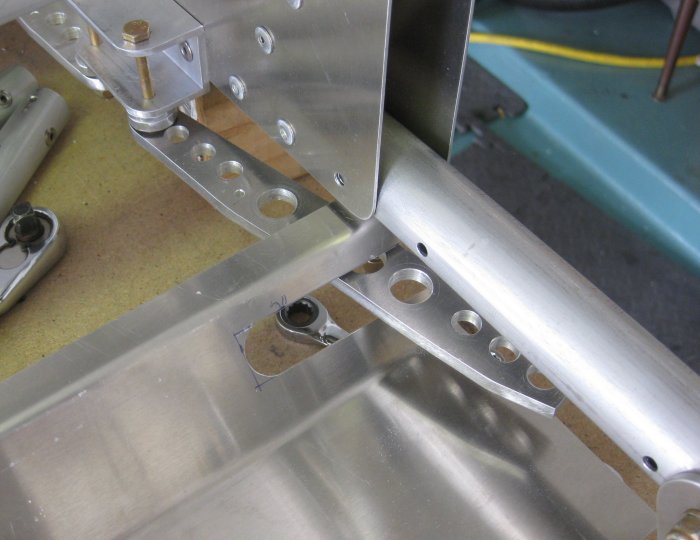
Left side, inboard looking outboard, forward to the right. Holes not to final size here. I stopped when I realized that the hole that goes through the tube for the quarter-inch bolt did not line up inside to outside. I am considering re-making the upper tube (and its inserts) as well as the outboard gusset plate. That should provide enough un-drilled locations to get this lined up again.
8/8/12 - forward section
1/4 hr - the days slip by if you don't keep plugging away. Deburred another tube. Found yet more holes not drilled to final size, so deburred all this just to re-hang the tube. Probably want a little more structure clecoed back on to line this up just right. Anyway, finding undrilled holes / unfinished holes is what happens when working on something in a million little increments.
8/9/12 - forard section
1/4 hr - clecoed triangulation tubes and mid-upper-longeron gusset plates into position and drilled these previously-missed 6 holes to final size. Located the remaining 1.0 x .065W that will be needed to re-make the FT20. There's more than enough.
8/10/12 - forward section
1/4 hr - pulled the remaining few tubes off the forward section for deburring. It is ~108 in the garage at this point, so that's another big reason work has been in short increments. Also started staging stuff in the garage to get another 33" out of the work area (cleared out 33" of junk at the end of the work table, so the work table can move down). This will be useful when the fuselage has the forward section permanently attached, and the aft section needs to be added.
8/11/12 - garage clean-up
Got a few more things moved around or thrown out that may help with carving out some more space for the project. So no direct progress today, but something that will pay off later.
8/12/12 - garage clean-up
Moved a shelving unit out of the garage to the hangar. That frees up a little more space, and gave me an idea for a couple more things that should probably go to the hangar.
8/15/12 - forward section
1/4 hr - must...keep...something...moving... Deburred a couple more parts. Cleaned up on the work table a little... So hot...
Not only looks like a lack of progress, but it looks like things are going backwards.
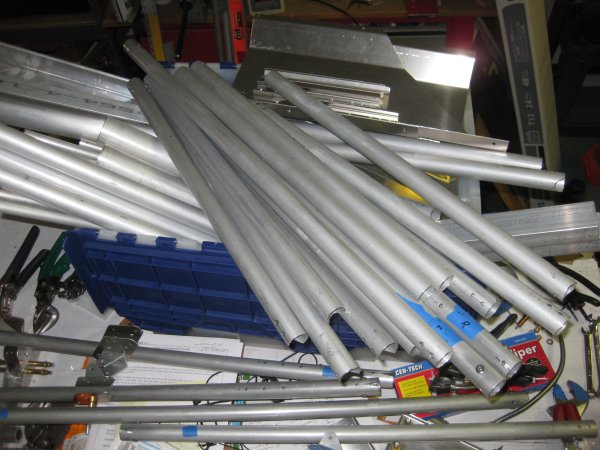
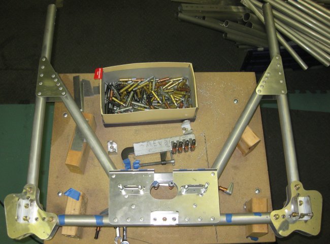
Big pile of final-size-drilled and deburred tubes & brackets.
8/18/12 - forward & mid sections
1 solid hour - Early before the kids got up. Took it way, way apart. Took out all the longerons and diagonals between the two central frames. Took the frames apart, top and bottom halfs. Need to complete drilling on the control column support gusset area (photos to follow), and the seat rail support brackets, and the pilot's rudder pedals. Found some parts in the Spruce catalog that should work at the rudder pedals, and as reported earlier, redesigned the pedals to a no-welding, all-aluminum configuration that I will be able to make with the tools I have. So though the project looks much less farther along, it is moving forwards.
Also took the Jabiru engine crate (from the Sonex) to the hangar.
8/18/12 - other activities
Gave the featured presentation at the EAA chapter meeting - some engines & airframes I'd run across at Oshkosh. Didn't have a projector for the slides, so all gathered in the first 3 rows of chairs and I put it full screen on the laptop. Fortunately I had also brought the full-page flyer for all but one of the products I was talking about, so I passed those around. I also got a solid two hours on cleaning up / rearranging the garage. Carol went shopping, the kids wanted to watch a movie (uncommon for a Saturday afternoon), and I had to meet a windshield repair guy out front. So with the Jabiru engine crate out of the way, as well as getting rid of some other stuff we're no longer using, I thought I had enough space to free up moving the 10-foot work table down by 33 or 34 inches. May not sound like much, but when this fuselage goes back together, that extra length in the work area will quickly be taken up by a growing fuselage.
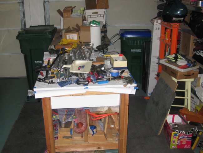
Work tables moved down 34 inches adjacent to the roll up door.
This is the table that will support the center box of the fuselage. Now there is room for both the forward section (to the firewall) and the aft section (the pilot's seat area) to be built up.
Aft side of the aft central frame.
Aft side of the forward central frame.
8/20/12 - center frame
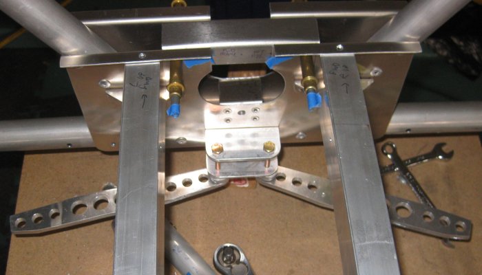
1/2 hr - started drilling the control stick supports. This is a little U-section bracket between the bottom center plates of the central frame. The U-section bracket also has back-up plates on each side, which are free-floating before being drilled. In short, this sucker is impossible to clamp in place - if the bottom center plate was riveted on. So good thing I didn't rivet those yet. The instruction book has these being added after the fuselage is put together - I have no idea how this would be done. I had to un-cleco the center plate, and clamp the U-bracket and backing plates with a c-clamp, then use a 12" drill bit to get the initial holes drilled. I don't trust that the center hole of the 5-hole pattern (the hole that becomes the through hole for the control stick mount) is actually aligned between the plates on the front and back of this central frame assembly, so I was thinking I might back-drill it (use one side as the pilot for the other side) on the drill press / pillar drill to get that one hole straight through. Then, the question becomes will this grouping of holes align between the two frames - 18" apart or whatever they are. This will be a test of the straightness of the entire fuselage assembly. Anyway, today got 1 side pilot drilled and started the first hole on the other side - but there's no way to clamp the backing plate, so I'll get it started and disassemble and c-clamp again.
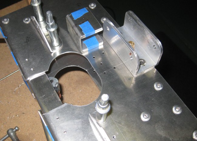
This is the U-bracket (with the blue tape) and its backing plates (held on with the blue tape) that sits inside that 5-hole pattern between the frame central plates. How to clamp this? How to clamp it enough to drill it?
8/22/12 - center frame
1/3 hr - accomplished the operations described above. Took some time to square up the U bracket, as it was a little over-bent on one leg, and a little under-bent on the other. This resulted in it sticking up into the volume where the control tube will go, and I don't know exactly where in the volume the control tube rides. So I figured it would be best to get that U bracket nicely out of the way because there's no point in grinding it down later (removes the strength of the U-bracket). Back-drilling the center hole for the 1/4" bolt that the control tube rides on worked nicely. Made a note on the other frame to also drill from aft-to-front so any misalignment between the forward and aft frames will be minimized.
8/23/12 - center frame
1/4 hr - marked and checked alignment on the U bracket assembly on the other (forward) center frame. This one looks a little better aligned between the front and back sides of the frame.
8/24/12 - center frame
3/4 hr - got a little time in early in the morning when it's not cool, but much cooler than trying to work at the end of the day. Got the U bracket parts drilled, drilled up to final size, and countersunk for the c-sunk rivets. Due to a U-bracket that is already riveted on, the microstop can't clear the two lower holes to be countersunk. Not a big deal. Will put the countersink cutter on a threaded drill bit extension and tweak the c-sinks by hand. Looking at the assembly print, the rivet heads don't have to be perfect as there are spacer washers on either side to reduce designed-in fore-aft float in the control stick assembly. A c-sunk head rivet can be completely structurally engaged with the thickness of the head material protruding above the surrounding surface, or the c-sink can be larger diameter than the rivet head to completely bury the head itself.
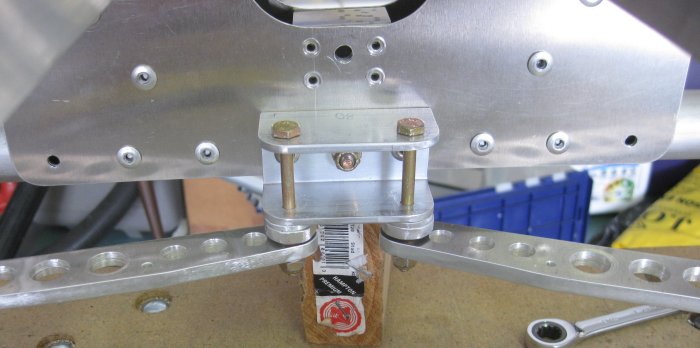
Forward frame, forward side - drilling and countersinking completed.
Forward frame, aft side - the lower two countersinks are slightly not deep enough. One answer is to do all this drilling/countersinking before riveting the bracket to the lower cross-tube. This would mean getting these U-bracket assemblies drilled in place before all the other build-up and drill to final size operations shown on this and the previous pages. Another answer would be a reduced-diameter micostop. Or the answer to be applied here - just finish the c-sinks by hand (on the pillar drill / drill press).
8/24/12 - center frame
1/2 hr - tweaked the two countersinks that needed a little more. Drilled the seat rail attach brackets to final size. Measured for locating marks and drilled the u-channel over the top of the control tube to pilot hole size.
8/25/12 - center frame
1/2 hr - drilled the u-channel over the top of the control tube to final size. Pulled it all apart and deburred. Clecoed it back together. Set it aside, and put the aft center frame on the table. I had pilot drilled some of the holes in that u-channel, but didn't mark the orientation. Tried both ways - neither was perfect, so picked the best. On up-sizing it will work out.
1/2 hr- drilled to final size one side of the aft center frame - upper u-channel & lower u-channel, including countersinking the 4 rivet holes on the lower u-channel.
8/26/12 - center frame
1/2 hr - Final size drilled the aft side of the aft center frame. Disassembled and deburred both sides and the two u-channel brackets and the doubler plates for the lower u-channel bracket. Noticed that there will still be a couple more holes added for the aft seat rails and aft seat rail support brackets. So will not rivet this side at this point.
Brought out the forward frame - should be able to rivet this one, pretty much. Noticed that the outer two holes along the bottom of the central plate already have rivets in them - drill those out. That's where the stringer supports eventually go. Also will up-drill the rudder pedal bracket attach points, then un-bolt one of the end plates to get the nylon plug back out in order to rattle out the chips and drilled-out rivet tails.
1/3 hr - pulled some rivets in the forward frame. Put one where a bolt went, so drilled that out and put the bolt in. While I had the drill with the right bit in it, drilled out 2 other rivets I had put in earlier that would need to come out. Now there's some rivet tails rattling around in the cross tube.
8/27/12 - center frame & engine mount beams
3/4 hr - could not recall where I had put the seat support beam brackets, so I moved on to set some of the rivets in the engine mount cross beams. In looking for parts, I found I had extra insert stock for the FT20 I need to re-make - the only insert size where I had made extra. Then I remembered the box where I had put the seat support beam brackets. Got those out and drilled to final size a couple of holes on the center frame that I had left at pilot size because they eventually get stringer support brackets. Concluded that it would be just as well to final size these now in order to debur the tube and plate - debur the stringer support bracket separately later. That's all I could stand in the heat today.
8/28/12 - center frame
1/2 hr - set rivets in the aft center frame. This marks 300 total hrs on the project.
8/29/12 - center frames
1/2 hr - drilled the pilot rudder pedal attach holes in the lower cross tube of the center frame. Installed a couple of brackets on the aft center frame. Installed the eye bolts that will get the forward seat seatbelt cables so as to not forget where the bolts are or where they go - there are doubler plates and stringer brackets that these bolts also will go through, but I packed the bolts up with washers for now. Clecoed the upper parts to the lower frame sections - time to start it in the getting bigger direction - to stay that way.
8/31/12 - center box
1/2 hr - reinstalled the side plates on the forward and aft frames. These are the ones that go on halfway up. Also put on the left side upper longeron tube between the frames to start to get the two frames connected back together. Seems like not much progress, but it takes time - I'm also cleaning off all the markings and making sure the bolts have the correct number of washers and that they are snugged down because I don't intend to be taking this apart again.
9/1/12 - center box
1/2 hr - Bolted more tubes onto the center box. As this goes together, I can see fasteners that will become difficult if not impossible to access, so need to consider the order. In particular, the aft outboard fasteners for the pilot foot rests get blocked by the diagonal tubes that mount the inboard corners of the foot rest. And I'm not sure if the seat rails themselves block access to the u-channels that close out the lower plates (over the control torque tube). Also want to drill the seat rails for the seat attachment brackets (which don't yet exist), so as to be able to clear any chips from inside the seat rail rectangular tubes.
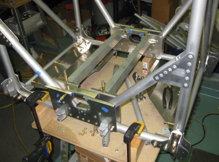
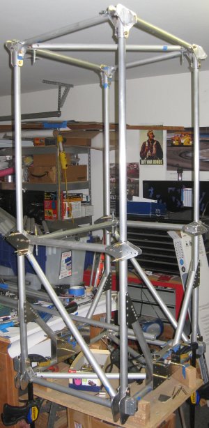
Center box, going back together, aft looking forwards.
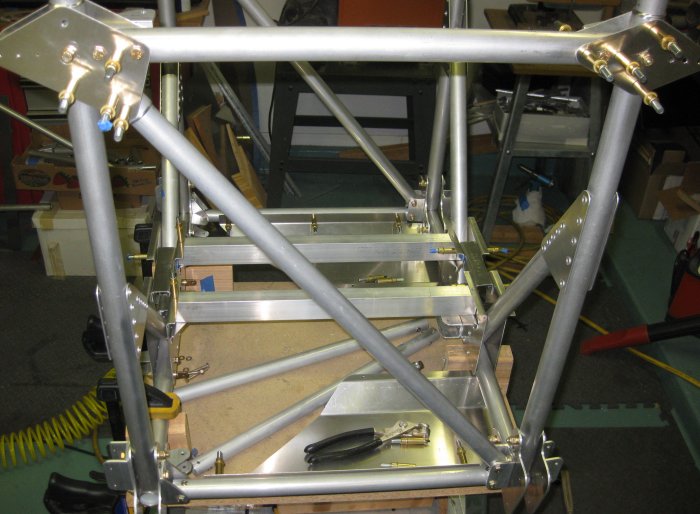
Center box, right side, forwards to the right.
9/2/12 - center box
1/2 hr - Marked and drilled locations for the front seat attach bolts on the front seat rails. To do this later would mean entrapped chips (or chips endlessly working their way out from the rails). The plans do not appear to specify exact points for this, so 3 inches back from the front of the rail then 5 1/2 inches back from those holes looked about right under the mockup seat. I put these holes 1/2 inch down from the top of the rail with the plan being to make brackets from 1x1x.125 angle to join to the seat bottom itself. Also found a few locations to rivet. So the box is now, well, if not permanent, at least a heck of a lot harder to take back apart.
9/4/12 - misc. parts
1/2 hr - made up spacers for the brake pedals. These set the pedals down a little lower. Also cut the tube inserts for the replacement FT20, so a little rework there.
9/5/12 - misc. parts
1/3 hr - sanded, filed, and scotchbrite-wheeled the spacers for the brake pedals.
9/6/12 - misc. parts
1/4 hr - drilled the spacers for the brake pedals.
Brake pedals hanging from the bracket (diagonal tubes go in the bracket, it's not just for the pedals).
Closer in view of the spacers for the pedals. Plans call for the spacers to be 3/4 dia. round rod, cut to 7mm length. I seriously doubt I could cut 3/4 dia. round rod on the band saw and have anything but approximately parallel sides on it, so I made the spacers from scraps of .188 and .090. This is within .003 of 7mm, and the sides that matter are perfectly flat and parallel. The OD's aren't quite as perfectly round, but that doesn't matter. Working with what you have to get what you want.
9/7/12 - center box, brake pedals, forward section
2 3/4 hr - Cut the replacement FT20 tube. Marked & drilled it for inserts. Riveted the inserts into this tube. Snugged up the brake pedals to locate the pedal slot. Swung the pedals back so they were towards the foot board, laid a ruler across the pedal to the foot board, and marked a line along the top and bottom of the pedal. Scaled from the drawing that the slot should go 3" back from the leading edge of the foot board. Marked the slot to be 3/4" wide, centered around the lines I drew for the top and bottom of the pedals. This results in the upper edge of the slot being about 1/2" down along the slanted inboard side of the foot board. Marked for a 3/4" diameter hole at the aft end of each slot. Drilled the 3/4" hole in each foot board with a unibit. Deburred these holes. Stacked a spacer board onto the platform of the band saw and cut the slots using the band saw. Filed the slot edges smooth with a file. Clecoed the foot boards into position. Pedals look like they will have plenty of clearance. Considering adding a doubler plate to the foot board, since the forward inboard corner of each foot board takes a good amount of the pilot's foot weight, but the brake pedal slot is a stress concentration at the upper aft corner of the slot. Bolted in the lower diagonals of the forward section, then the upper longerons of the forward section. Got the FT20's in place on each side - the brand new one I made appears to be ~2mm short! But with a slight leaning on the structure, it should pull in just right. Bolted in the FT26 cross-tube and the FT28B aft upper diagonals. Doing this brought the FT20 even closer to fitting just perfectly. Next step - remake the outboard gusset plate for the bottom/forward end of the FT20. (Yes, I do make a list of what I'm going to do ahead of time, so I don't spend a lot of time thinking about what to do next while I'm doing it.)
Pedal full back - when I add a doubler plate, it will be cut parallel to the back of the pedal to act as a stop. Plans say back of the slot is the stop. Note the slight angle cut on the outer inch or so of the pedal. Makes sense in this orientation.
Pedal parallel with the fuselage frame. Guessing this is about mid-travel.
Mid-travel, another view.
Guessing this is about as far forward as it can go.
Ok, seeing it in photos now - where's the forward stringer support going to go? Need to check on that. Looks like the pilot's foot board and the brake pedal both interfere with where the stringer support is shown in the plans. I hope I'm missing something.
1/2 hr - drilled the lower inboard end of the FT20 to no. 12 to cleco to the upper longeron bracket. Cut out lower portion of a replacement upper longeron bracket. Left the upper portion oversize to allow for drilling straight through the tube - not sure where the hole will end up in the bracket. Received small package of material - some 1/4 x 3/4 bar stock, 1/4 x 1/2 bar stock, 3/4 square bar, 3/8 x 1 bar, and the 3 x 3 x .125 square tube for the rudder pedals.
Click to join sherwoodbuilders