Sherwood Ranger - Fuselage - 8
*This web site is NOT owned or managed by G-TLAC. G-TLAC is not responsible for the content unless explicitly stated. See Disclaimer.
10/28/12 - Seat rail check
Picking up where I left off... Note to self - the spacer for the lower cross tube should/will go above the tube, making it .125 lower. Reason - I checked the pilot's seat rail, and it angles up slightly to the rear. I don't think this would matter, but given the opportunity to bring the aft end down a little, I will take it.
1/2 hr - added spacers on the top side of the lower cross tube (FT35) to move it down. This helps the slight upward slope to the rear on the seat rails just a little. Rounded the upper forward edges of the seat rails so they would fit tighter to the plate on the aft frame of the center box. Measured back along the rails to the elevator bell crank support point. Got out that small piece of square tube and measured for 45-degree angle cuts on each end.
10/30/12 - aft structure
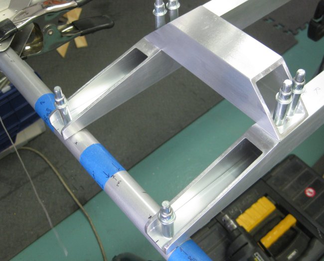
1/2 hr - drilled the aft seat rails to the center box, top fastener only. Not sure how I will turn this thing to give improved access to the small brackets below the seat rails - maybe just clamp as best I can, do the pilot holes with the 12-inch drill bits, and use the right-angle drill from there. Also cut the elevator bell-crank support - this is a 1.25 square tube cut at 45 degrees each end, total length 165mm to sit on top of the seat rails. The angled diagonals down to the seat rails do not have a dimension to where along the rail they go - will measure the prints.
10/31/12 - aft structure
1/2 hr - smoothed off the cuts on the elevator bell-crank support tube. Marked and pilot drilled this tube, then located it on the seat rails and pilot drilled it to those. Tried to locate the seat rail support tubes - I believe these are FT29, but I can't find a figure to indicate this. Though these should be FT29 by elimination - I can see where FT26, 27, 28 go (up front), and where 30, 31, 32 go (in the aft structure area).
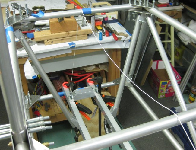
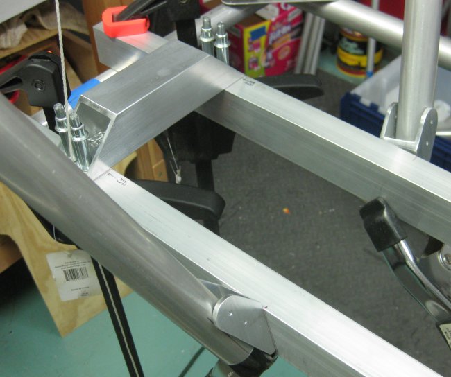
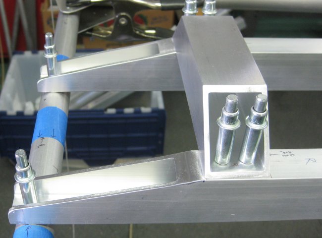
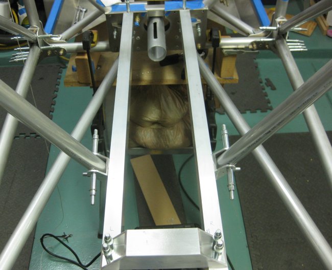
Aft seat rails in position.
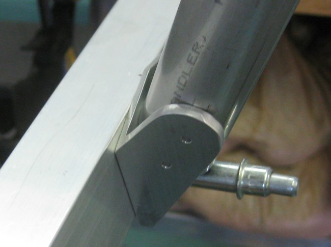
Elevator bellcrank support.
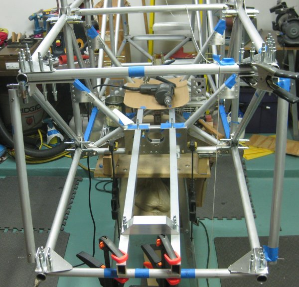
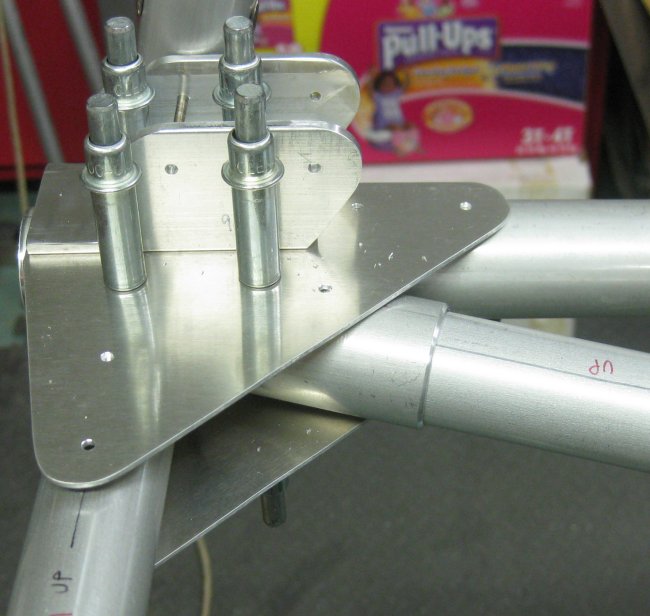
View aft looking forwards.
11/1/12 - aft structure
3/4 hr - could not find the protractor I had been using, but found another one. Probably achieved about the same accuracy. Best I could tell, the FT29 tubes angle at 14 degrees forward. This angle is achieved in-plane (don't have to worry about the angling inboard of the FT29's) where the U-channel bracket for the FT29 tube sits on the other U-channel bracket at the upper end. So laid out the hole in the U-channel bracket for the FT29 bracket, drilled that, drew parallel lines 5/8" to either side of the hole centerline at my best measurement of 14 degrees, and clecoed the FT29 bracket on. Then spent time fish-mouthing the upper end of both FT29's to sit into their attaching U-channel brackets. Clecoed the upper end of the FT29's into position. Set the lower ends into place. The lower ends will also need relief to fit into the attach brackets.
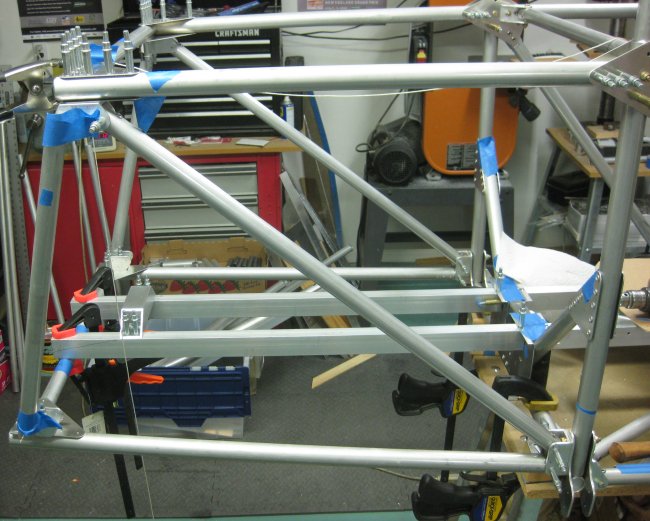
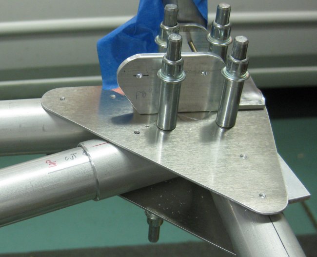
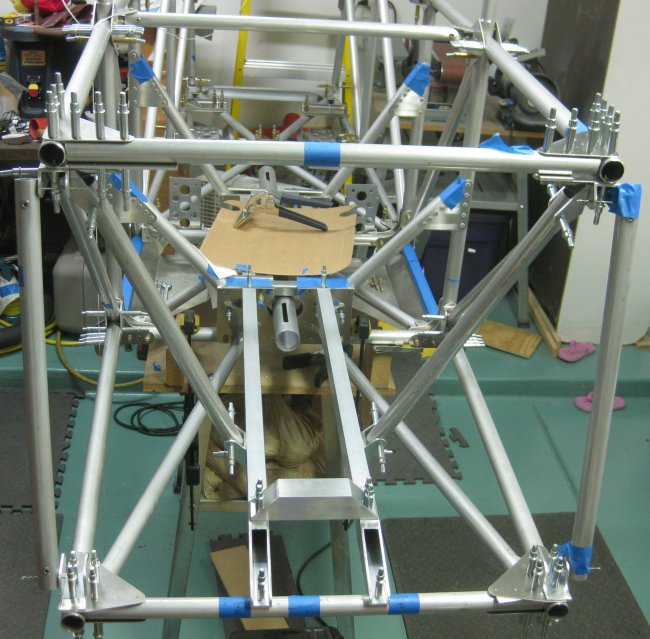
FT29 tubes set approximately in position.
FT29 tubes to the seat rails, forward looking aft.
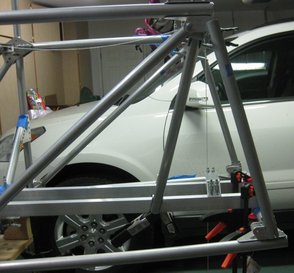
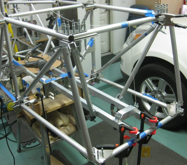
Left side view. The other FT29 tube is hidden behind the left one.
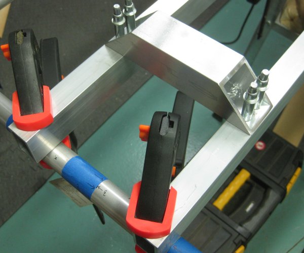
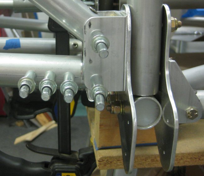
Upper FT29 attach bracket, left side.
Upper FT29 attach bracket, right side.
Lower FT29 brackets set into position. Tubes need to be angle-trimmed to seat all the way into the brackets.
11/3/12 - forward structure
1/2 hr - drilled the lower aft longerons to the insert tubes at the forward end - noticed in shifting things around that the lower longerons were tending to pull aft. So put a thin cardboard (~.020") spacer between the end of the longeron and the U-channel bracket on the center frame (so the lower longeron won't sit directly against the u-channel bracket) and drilled the outboard 3 holes on each longeron to pilot size. Then, since the lower engine mount cross beam had just been placed on the structure, I took the time to get the engine mount bolt inserts into the lower longerons and worked the cross beam into place, and installed the bolts through it so it is fastened to the lower forward longerons. Then clecoed the front-seater foot rests in place - this reminded me that they share a fastener hole with the FT26 cross-tube. Then clecoed the rudder pedal mount brackets in place (so I don't misplace them), and set the rudder pedals up there. Again, since I am not using the welded steel rudder pedals there is a bit of a compromise on their inboard-outboard position. Will need to think about that - make a different inboard mounting bracket? Use a small spacer on the pedal attach bolt? Either way, it shouldn't be hard to achieve an acceptable position for them.
Industrial Metal Supply - went to the IMS grand opening in Tucson today. Looks like they have in stock quite a bit of 6061-T6 plate in various thicknesses. Looks like .032 is the thinnest in stock, but there was a spot in the rack for .025, and I would expect they could get that on order. I bought a 12' stick of .875 x .875 to use in fabbing the aft fuselage u-channel brackets. It seems as though .875 x .875 x .125W u-channel does not exist in 6061. Oh, and with this, got a free lunch, a free T-shirt, and a car show...
1/2 hr - after remembering that WD40 is the magic product for cleaning off adhesive tape glue, I cleaned off the square stock that I got from the IMS today. Marked and cut the aft seat rails. Cut them off flush with the FT35 cross-tube. The view in the plans shows maybe 1/8" shorter than that. The side view in the plans also implies that these rails are cut down to essentially zero thickness at the aft end. I suppose this would work, as the FT29's would take the weight of the pilot, but I tapered them down to 1/2" high cross section at the aft end just so there would be a little more bending resistance there.
3/4 hr - marked and drilled the aft end of the rear seat support tubes to the FT35 lower cross tube. Drilled the lower RH FT29 attach bracket to the rear seat support tube. Marked and cut the FT29 to length (as shown in the print, it's 7-8mm too long, and is marked as cut/drill in place). Filed the angled relief into the lower end, and after a couple of test fittings, got the tube reasonably well seated into the lower mount bracket.
11/5/12 - aft section
1/2 hr - clamped up and pilot drilled the aft seat rail support brackets. Note - need to strike a line between fasteners on the plate so the bracket is positioned such that one of the bracket fasteners also goes through the diagonal tube. Cut tubular spacers for the FT36's. Went with 50mm long. Started to put one of the FT36's into position, but it will take quite a relief cut to fit into the lower aft corner brackets. Marked and drilled the LH FT29 lower attach bracket. This is another one where the tube itself needs a good bit of relief to fit into the bracket, so I'll leave that for another time.
11/6/12 - aft section
1 1/2 hr - fitted the FT36's and the lower end of the LH FT29. For the FT36's, I fit the tubular spacer to the aft gusset plates first - drill holes 180 deg. apart, 10mm from the end, then trim as required so the more forward hole lines up along a line drawn along the tubular spacer from the aft holes. With that, you know the tubular spacer will fit. Then inserted the FT36 into the forward bracket. Saw somewhere that this bracket, if rotated, will allow the FT36 to rise at the slight angle needed to meet the aft bracket. Eyeballed the length for the FT36 (it is defined at ~10-12mm too long, to be cut to length on installation). Remove the FT35 cross-tube to be able to see the back end of the FT36. Be aware that without the FT35, the lower longeron can swing inboard/outboard, so positioning from here is approximate.
Cut the FT36 to length, then angled it in next to the tubular spacer which is clecoed in position. Saw that the FT36 was ~2mm longer than the angled spacer. Mark inboard, and vertical up/down points on the FT36 (where it contacts the upper and lower gusset plates). Then pull the FT36 off the assembly, pull off the tubular spacer. Locate the tubular spacer on the FT36 aligning the up/down lines with the holes in the tubular spacer. Then trace through the fish mouth / angled cut on the tubular spacer onto the FT36. Cut the marked off area of FT36 on the band saw. Touched it up with a file. Clecoed everything back together - the FT36 fit inside the tubular spacer. Aligned the holes in the tubular spacer with the holes in the gusset plate and drilled through the FT36 tube. Repeated this for the other side. Actually pretty easy after figuring out all the moves to make to get the first one fitted. Got the upper and lower aft longerons (for the tail portion of the fuselage) out of storage. Set them in position on the right side, since I could prop them up on the work table for approximate support. This is a nice-sized fuselage. Should be able to carry two pretty big people.
FT36 with tubular spacer, left side.
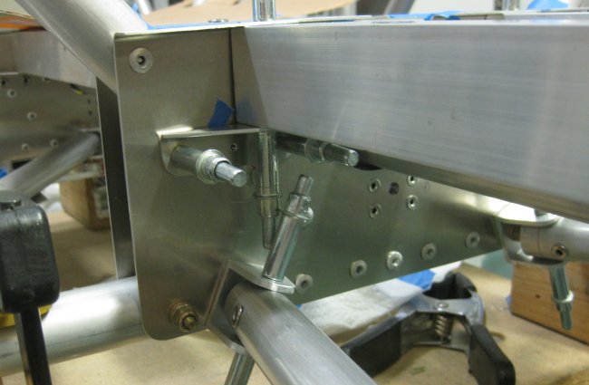
FT36 with tubular spacer, right side.
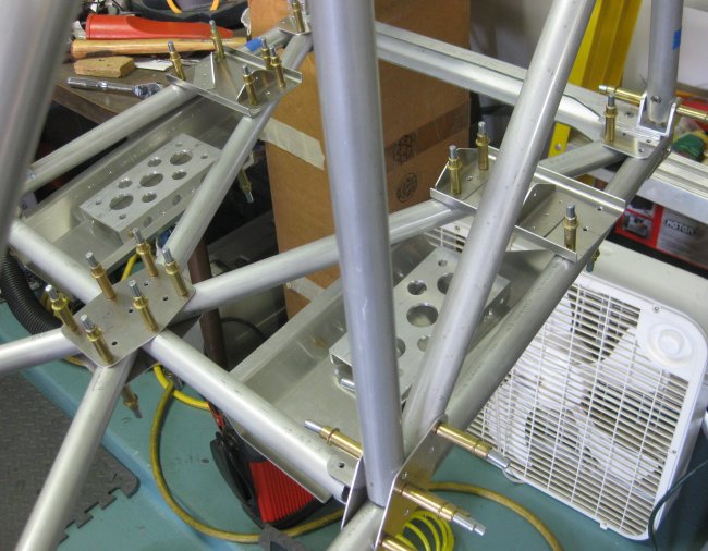
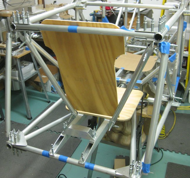
FT29's rising up from the seat rails, FT36's attach below the seat rails.
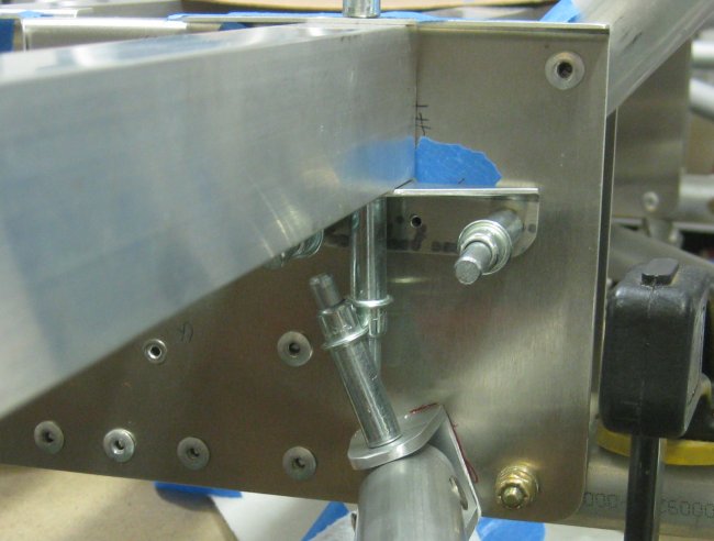
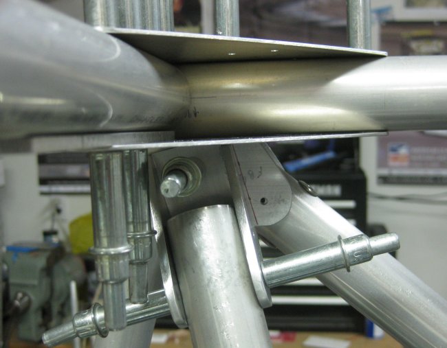
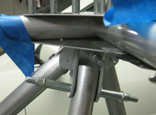
FT36 attach bracket - rotated to allow tube to angle upwards towards the aft end.
FT36 attach bracket, left side.
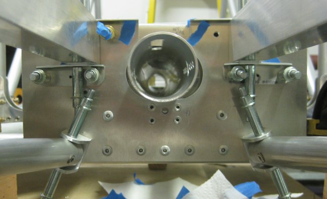
Fuselage frame center plate showing rotation of FT36 attach brackets.
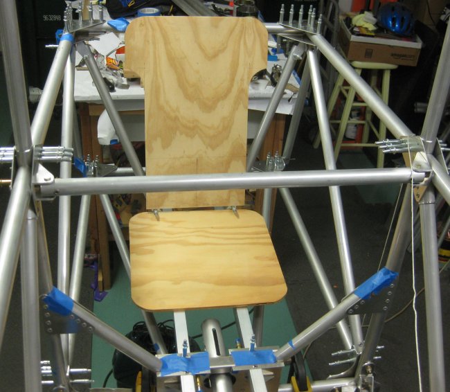
Mock-up pilot's seat in position.
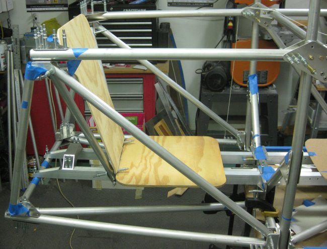
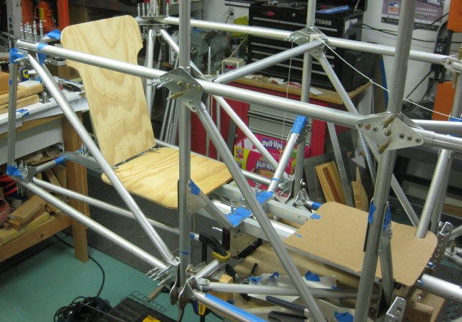
Pilot's seat, side view.
11/7/12 - aft section
3/4 hr - here's where the appearance of things won't change very much. Found some .125 strip at 19/32" wide. Probably from cutting one side out of square tube to make u-channel, but that saves cutting a bunch of straight-line cuts to make up the final spacers for the FT34 and FT35 installations. Cut these to length to fit under the gusset plates. For whatever reason, 68mm worked for the lower tube, and 70mm for the upper. Smoothed the edges and marked a centerline on each spacer. Marked 10mm from the end, and drilled a locator hole in each spacer. Then inserted the spacer between the tube and the gusset plate, lining up the hole in the spacer with the hole in the gusset. Then aligned the spacer using the centerline, sighting through the holes in the gusset plate. Spent the rest of the time drilling pilot holes that had not been drilled through all parts. Still have a couple more to go, and there is a little structure between the seat rails at the FT29 attach brackets to be added.
11/9/12 - aft section
1/2 hr - drilled the 2nd holes in 3 of the 4 FT29 brackets. Kept them lined up by clamping pieces of .188 stock on either side of the bracket before removing the FT29 tube. Seems like it worked pretty well. Took 1 of the brackets up to final size and riveted it on.
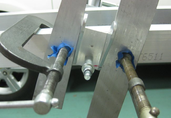
Got the lower hole drilled through the bracket into the seat rail. This allows the bracket to pivot to perfectly align with the FT29 tube. How to keep it that way to drill the second hole in the bracket which locks the direction of the bracket? Scrap clamped to either side of the bracket holds it in place while the tube is removed.
11/10/12 - aft section
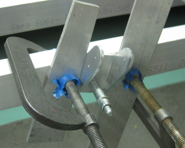
1/4 hr - drilled the 2nd hole & final sized the 4th of the 4 FT29 brackets. Same idea - kept the bracket aligned by clamping small pieces of scrap on either side before pulling the FT29 out.
1/2 hr - drilled some of the lower aft holes to final size - FT35 and the FT36's, upper side. Running out of 3/16 clecoes again. Puzzling out what can and can not be drilled out at this stage as the longerons to the tail need to go into place and get drilled. Also what can and can not be riveted.
11/11/12 - computer work
Moved the files for this site to another computer, including download & installation of a new FTP app. Made a sample upload. Looks like I can maintain the site from the new computer.
End of this page
Click to join sherwoodbuilders