Sonex* Instrument Panel
*This web site is NOT owned or managed by Sonex, Ltd.. Sonex, Ltd. is not responsible for the content unless explicitly stated. See Disclaimer.
These panel pictures are included for documentation. This area of the airframe has been revised more than any other, and even then is fairly easily modified to suit the individual builder. The panel includes a structural cross member along its bottom edge, but other than that, people are doing different things with it.
What I have shown here was built to the original prints. They have since changed to a single-piece panel, and on the 3300-powered taildragger prototype, have simplified the panel about as much as possible: a single all-in-one engine/flight instrument, and a radio.
One item on this page that I think may still have some significance is my mod to the panel side brackets - if you cut the fuselage side angles prior to their length revision, these side brackets make up the difference. 11/22/00.
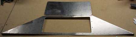
Panel assembly. The number of screws connecting the panel insert to the panel frame fastens the insert very solidly. 12/5/99
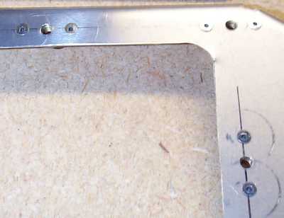
Showing countersunk rivets for nutplates. The circular marks around the lower right c-sunk rivets are from the microstop. These should clean up, but I want to paint it all black anyway. 12/5/99
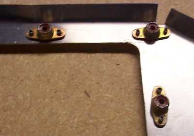
Nutplates (back of panel). 12/5/99
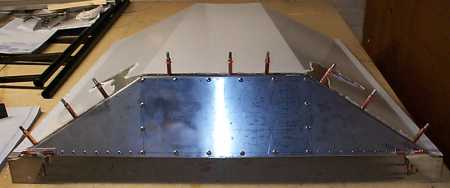
Panel assembly with glare shield. 1/14/00
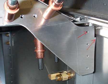
Detail of right side panel corner bracket. Arrows show top of F14-08 & rivet hole that won't attach to anything. This was noted some time back in the digest (#172?). I missed the note. The F14 print may have been revised by now. You would know because the F14-08 should be about an inch longer than the aft wing attach angle (F14-09?). 1/17/00
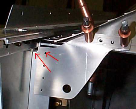
Detail of left side panel corner bracket. Glareshield is not clamped/clecoed to upper angle of cockpit side, so the bracket actually sits higher than shown. 1/17/00
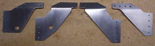
I am not going to re-do the F14-08's (riveted in, non-90 deg. angle), so I re designed the F07-07's. These extend down to the F14-08's just right. Putting the bracket edges perpendicular to the bend reduces residual stress in the part - they take less force to bend, & it is easier to keep the bend on the bend lines. (New brackets move top rivet hole down 1 1/2 hole spaces.) 1/29/00
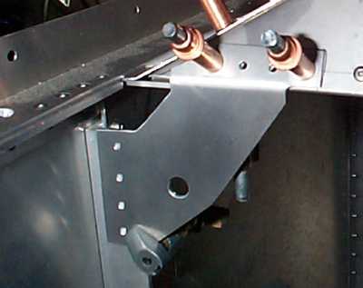
Re-designed F07-07, left side, installed position. 2/27/00
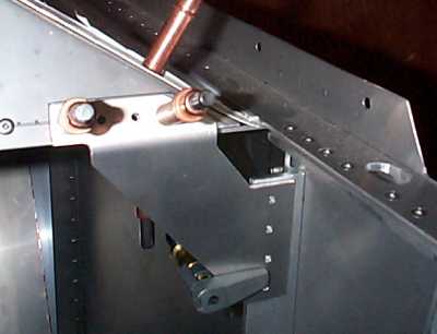
Re-designed F07-07, right side, installed position. 2/27/00
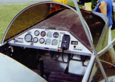
Panel of first airframe, Sun N Fun 1998.
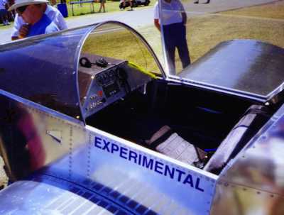
Panel of 6 cylinder airframe, Sun N Fun 1999.
Changed to multi function instrument to reduce number of small round instruments.
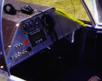
Close up of newer panel design.
Now that I'm making these parts, I see that the panels in these prototypes do not reflect the design change to raise the bottom of the panel for more leg room. Design has been changed to move that bottom flange (with the row of rivets) up onto the face of the panel. Panel bottom is now where the bend in the panel is in these airplanes.