Sonex* Variations 2
*This web site is NOT owned or managed by Sonex, Ltd.. Sonex, Ltd. is not responsible for the content unless explicitly stated. See Disclaimer.
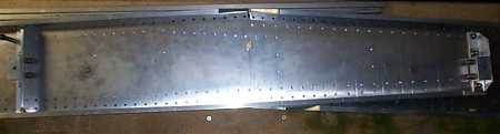
Along the top of the spar, one of the patterns was changed from something like 15 rivets instead of 15 spaces (16 rivets) - so with 2 rows along the top of the spar, that's 2 rivets omitted per spar. I checked with Sonex on this - they can not "approve" such a change, but pointed out that the rivet spacing was changed by .050" or less between the 15 rivets - within a reasonable tolerance of rivet placement. This is not in the area of the wing which failed when they did their load test to destruction - and is in the thickest, heaviest part of the spar. (Spar top at bottom of picture.)
Another view.
6 extra holes in the tail post, drilled to 1/8. When the vertical tail is permanently installed, these will be filled with CCP-6 rivets.
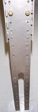
Another view of the extra holes in the vertical tail post on the vertical fin.
6th wing skin came up a tiny bit short on material (I had cut another part out of a sheet I forgot was reserved for a wing skin). The missing area is about 2" x 6", on a diagonal. I placed this patch/splice to be on the forward edge of the bottom skin, at the wing tip (a lightly stressed area). The splice is about 4" x 10" - picking up the row of rivets from the next rib bay over, and includes enough rivets (26 additional) to be stronger than the original part. Also at this point, easy enough to use this skin as a trace/drill guide to replace with a clean sheet.
3 pilot holes on the vertical tailcone c-channel were too high for the cross beam. Redrilled below original row.
Same thing, another location.
Same thing, another location.
Same thing, another location.
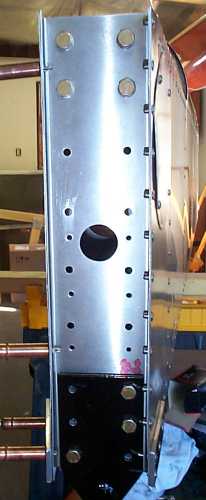
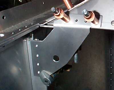
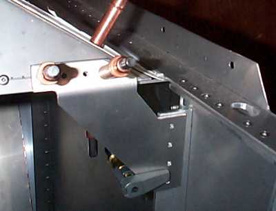
Just ahead of the root rib angle in the picture, between the countersunk bolts, there are 2 extra pilot holes (lightly marked with X's). This is an error in laying out the spar webs. I left these at 3/32. Due to their location (mount block angle on one side, the other spar on the other side) they can't be filled. Both spars have this.
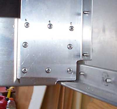
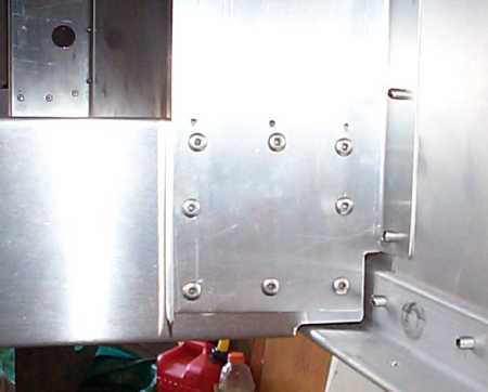
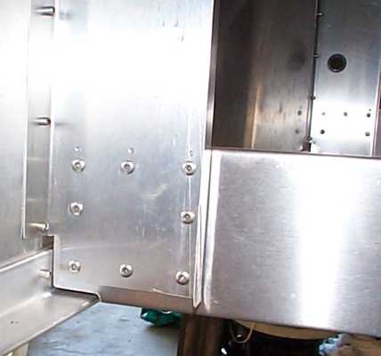
Other non-structural variations: the below panel gussets were changed.
There is a known correction to the print for these, but since I had already installed the vertical fuselage angles before the correction was issued, I chose a mod which would not require drilling out the parts already installed. (I also redesigned the gussets to have less residual stress after bending than those in the print.)
Installed the turtledeck upper c-channel with the c inverted from print. This required reversing the clips to the turtledeck formers, but is structurally equivalent.
Turtledeck skin has a few indentations at rivet locations due to rivet pulling skin against turtledeck former. 2 proposed solutions: with a block drilled to fit around the rivet from the inside, hammer out the indentations, or drill out the rivets, create a spacer, and re-rivet. I prefer either the first option (which I was told another Sonex builder has used), or just leaving things as-is. I think that unlike RV's which can use body filler & paint to mask riveting discrepancies, a from-plans hand-formed machine like the Sonex will probably have just a few things which indicate its hand-formed nature.
Again, please don't consider ANY of this acceptable for your airplane. This is presented for documentation of my build only.